Feature description, Austin microlynx – GE Industrial Solutions Austin Microlynx SIP User Manual
Page 12
Data Sheet
July 2, 2010
Austin MicroLynx
TM
SIP Non-isolated Power Modules:
3 – 5.5Vdc input; 0.75Vdc to 3.63Vdc Output; 5A output current
LINEAGE
POWER
12
Feature Description
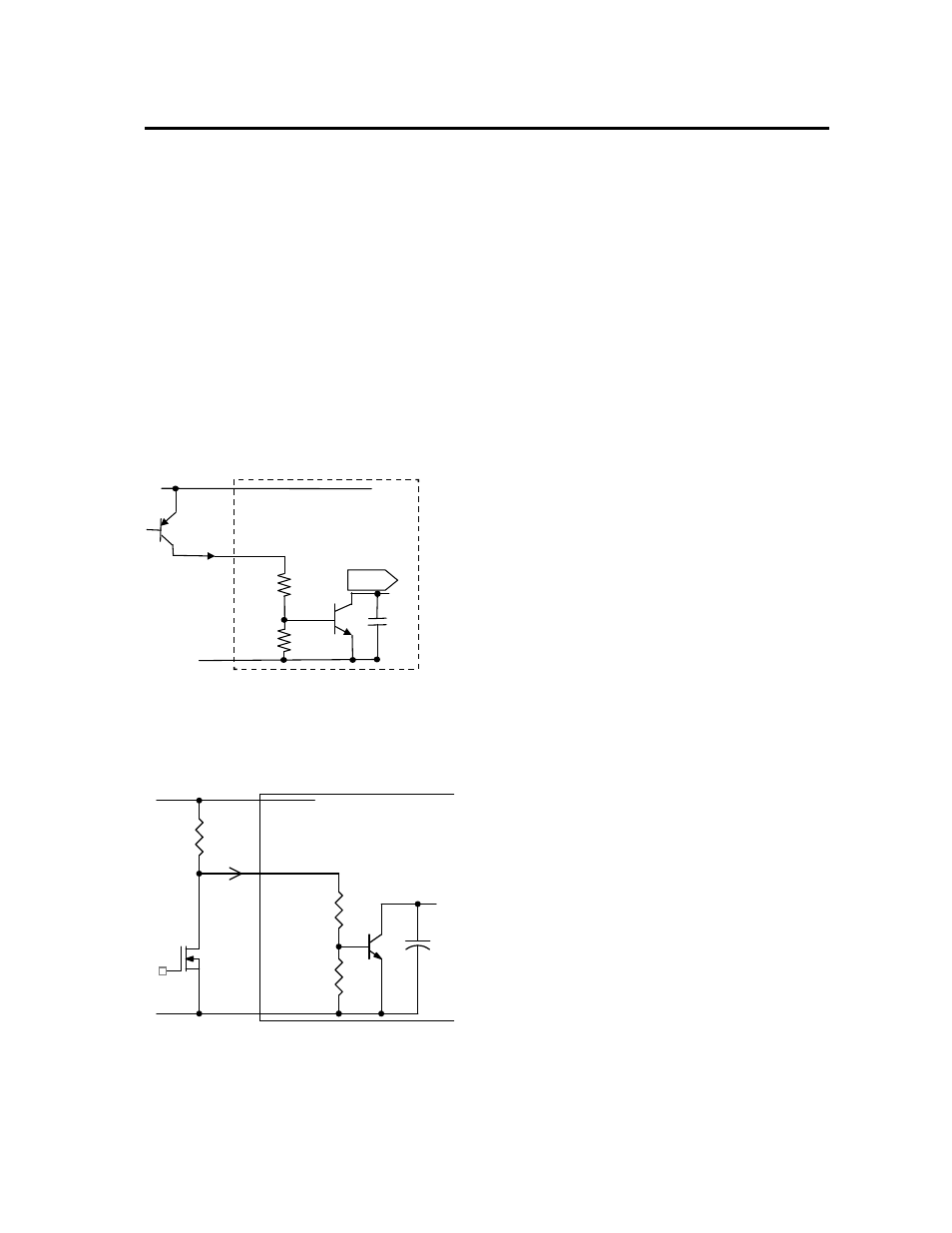
Remote On/Off
The Austin MicroLynx
TM
SIP power modules feature an
On/Off pin for remote On/Off operation of the module. If
not using the remote On/Off pin, leave the pin open
(module will be On). The On/Off pin signal (Von/Off) is
referenced to ground. To switch module on and off using
remote On/Off, connect an open collector pnp transistor
between the On/Off pin and the V
IN
pin (See Figure 28).
When the transistor Q1 is in the OFF state, the power
module is ON (Logic Low on the On/Off pin of the
module) and the maximum Von/off of the module is 0.4 V.
The maximum allowable leakage current of the transistor
when Von/off = 0.4V and V
IN
= V
IN,max
is 10μA. During a
logic-high when the transistor is in the active state, the
power module is OFF. During this state VOn/Off =10 -
14V and the maximum IOn/Off = 1mA.
V
IN
(+)
GND
Enable
20k
20k
On/Off
Pin
Css
I
On/Off
Lynx-series Module
Figure 28. Remote On/Off Implementation
Remote On/Off can also be implemented using open-
collector logic devices with an external pull-up resistor.
Figure 28a shows the circuit configuration using this
approach. Pull-up resistor, R
pull-up
, for the configuration
should be 5k (+/-5%) for proper operation of the module
over the entire temperature range.
Figure 28a. Remote On/Off Implementation using
logic-level devices and an external pull-up resistor
Overcurrent Protection
To provide protection in a fault (output overload)
condition, the unit is equipped with internal
current-limiting circuitry and can endure current limiting
continuously. At the point of current-limit inception, the
unit enters hiccup mode. The unit operates normally once
the output current is brought back into its specified range.
The typical average output current during hiccup is 2A.
Input Undervoltage Lockout
At input voltages below the input undervoltage lockout
limit, module operation is disabled. The module will begin
to operate at an input voltage above the undervoltage
lockout turn-on threshold.
Overtemperature Protection
To provide over temperature protection in a fault
condition, the unit relies upon the thermal protection
feature of the controller IC. The unit will shutdown if the
thermal reference point T
ref2
, (see Figure 31) exceeds
150
o
C (typical), but the thermal shutdown is not intended
as a guarantee that the unit will survive temperatures
beyond its rating. The module will automatically restarts
after it cools down.
Q1
R1
R2
Q2
CSS
GND
PWM Enable
ON/OFF
VIN+
ON/OFF
_
+
V
I
MODULE
pull-up
R
ON/OFF