GE Industrial Solutions Spectra Series Power Panelboards ATVS Tranquel User Manual
Page 2
2
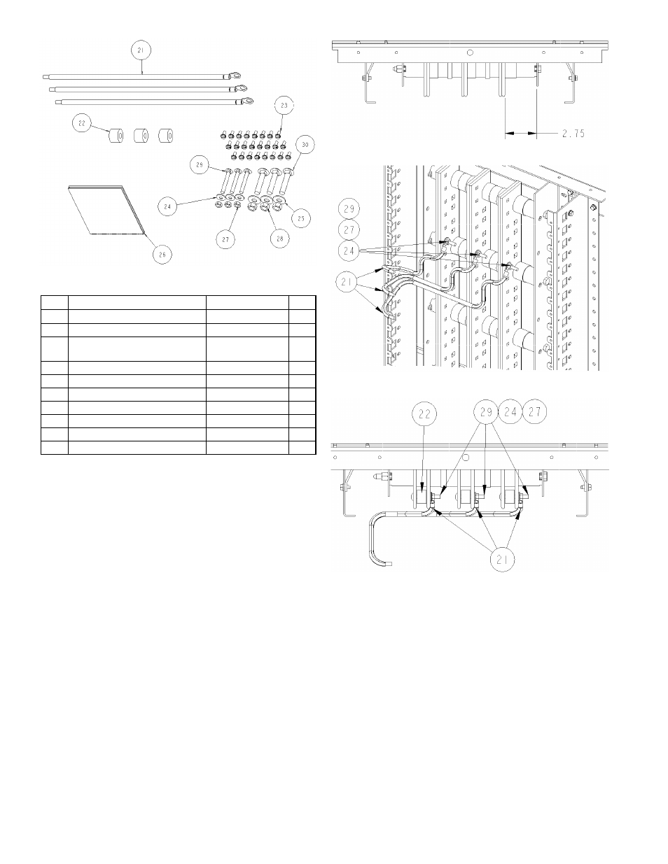
Figure 2. Hardware included in [2].
Item Description
Part #
Qty.
21
Cable assembly
10080819P2
3
22
Spacer, .70 inch
188A4381P9
3
23
Thread-forming screw,
10-32 x
7
/
16
"
192A6976P189
24
24
Conical spring washer,
1
/
4
"
75A105503P101
3
25
Conical spring washer,
3
/
8
"
75A105503P102
3
26
TVSS instruction sheet
DEH223
1
27
Nut,
1
/
4
-20
N245P21B6
3
28
Nut,
3
/
8
-16
N245P25B6
3
29
Carriage bolt,
1
/
4
-20 x 2"
N657P21032B6
3
30
Carriage bolt,
3
/
8
-16 x 2"
N657P25032B6
3
Table 3. Parts list for the hardware package [2].
2. Install TVSS-bus cable assembly.
(For connecting a
TVSS to a disconnect, go to step 2.)
• Bolt-on and single bus of plug-in assemblies, switchboard
panels, and powerpanel. Before installing, locate the
side of the panel interior for which the dimension
from the nearest vertical bus face to the inner face
of the bus support rail is 2.75 inches, as indicated
in Figure 3. The cable terminals will be mounted
on this side of the bus.
For each phase install a
1
/
4
-20 x 2" carriage bolt
[29] into a .281-inch square hole of the interior
vertical bus, as shown in Figure 4. Use the
uppermost holes in the 7X (9
5
/
8
") space that the
TVSS unit can reach. Slide a terminal of the cable
assembly [21] onto each carriage bolt and rotate it
so that the terminal barrel is located below the front
edge of the vertical bus. Install a
1
/
4
" spring washer
[24] and a
1
/
4
-20 nut [27] onto each bolt and
tighten to 75 in-lb.
• Plug-in assemblies, switchboard panels, and panelboards
with .281-inch square holes available (double bus). For
each phase, slide a spacer [22] between the vertical
bus bars and install a
1
/
4
-20 x 2" carriage bolt [29]
into a .281-inch square hole located towards the
front of interior vertical bus, as shown in Figure 5.
Use the uppermost holes in the 7X (9
5
/
8
") space
that the TVSS unit can reach.
Figure 3. Top view of a bolt-on interior.
Figure 4. Bolt-on and single-bus plug-in assemblies.
Figure 5. Plug-in assemblies with .281-inch square holes.
Slide a terminal of the cable assembly [21] onto
each carriage bolt and rotate it so that the terminal
barrel is located below the front edge of the vertical
bus. Install a
1
/
4
" spring washer [24] and a
1
/
4
-20
nut [27] onto each bolt and tighten to 75 in-lb.
• Plug-in assemblies and powerpanels without .281-inch
square holes (double bus). For each phase, slide a
spacer [22] between the vertical bus bars and
install a
3
/
8
-16 x 2" carriage bolt [30] into a .406-
inch square hole located towards the rear of
interior vertical bus, as shown in Figure 6. Use the
uppermost holes in the 7X (9
5
/
8
") space that the
TVSS unit can reach. Slide a terminal of the cable
assembly [21] onto each carriage bolt. Install a
3
/
8
"
spring washer [25] and a
3
/
8
-16 nut [28] onto each
bolt and tighten to 200 in-lb.