Data sheet, Thermal considerations (continued) – GE Industrial Solutions EBDW025A0B Barracuda Series User Manual
Page 12
GE
Data Sheet
EBDW025A0B Barracuda™ Series; DC-DC Converter Power Modules
36-75Vdc Input; 12.0Vdc, 25.0A, 300W Output
April 15, 2013
©2012 General Electric Company. All rights reserved.
Page 12
Thermal Considerations (continued)
temperature, as defined in IPC-9592. This procedure is then
repeated for a different airflow or ambient temperature until a
family of module output derating curves is obtained.
Heat-dissipating components are mounted on the top side of
the module. Heat is removed by conduction, convection and
radiation to the surrounding environment. Proper cooling can
be verified by measuring the thermal reference
temperature
(TH
1
or TH
2
). Peak temperature occurs at the position indicated
in Figure 18 and 19. For reliable operation this temperature
should not exceed TH
1
=125°C or TH
2
=105°C. For extremely
high reliability you can limit this temperature to a lower value.
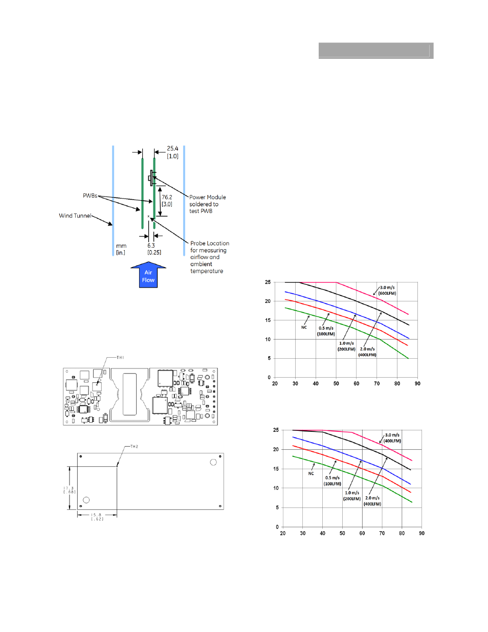
Figure 18. Location of the thermal reference temperature
TH.
Figure 19. Location of the thermal reference temperature
TH3 for Baseplate module.
The output power of the module should not exceed the rated
power for the module as listed in the Ordering Information
table.
Please refer to the Application Note “Thermal Characterization
Process For Open-Frame Board-Mounted Power Modules”
for a detailed discussion of thermal aspects including
maximum device temperatures.
Heat Transfer via Convection
Increased airflow over the module enhances the heat transfer
via convection. The thermal derating of figure 20-22 shows
the maximum output current that can be delivered by each
module in the indicated orientation without exceeding the
maximum TH
x
temperature versus local ambient temperature
(T
A
) for several air flow conditions.
The use of Figure 20 is shown in the following example:
Example
What is the minimum airflow necessary for a EBDW025A0B
operating at V
I
= 48 V, an output current of 20A, and a
maximum ambient temperature of 60 °C in transverse
orientation.
Solution: Given: V
in
= 48V, I
O
= 20A, T
A
= 60 °C
Determine required airflow velocity (Use Figure 20):
Velocity = 2.0m/s (400 LFM) or greater.
O
U
TP
UT C
U
RRE
NT, I
O
(A)
LOCAL AMBIENT TEMPERATURE, T
A
(C)
Figure 20. Output Current Derating for the Open Frame
EBDW025A0B in the Transverse Orientation; Airflow
Direction from Vin(+) to Vin(-); Vin = 48V.
O
U
TP
UT C
U
RRE
NT, I
O
(A)
LOCAL AMBIENT TEMPERATURE, T
A
(C)
Figure 21. Output Current Derating for the Base plate
EBDW025A0B-H in the Transverse Orientation; Airflow
Direction from Vin(+) to Vin(-); Vin = 48V.