Protrip™ trip units chapter 2. trip unit setup, 2–7 ground-fault pickup, 2–8 ground-fault delay – GE Industrial Solutions ProTrip Trip Units for Low-Voltage User Manual
Page 13: 2–9 defeatable ground fault
ProTrip™ Trip Units
Chapter 2. Trip Unit Setup
7
2–7 Ground-Fault Pickup
This function sets the pickup current for ground-fault
protection. The available settings are listed in Table 10 as
multiples of X, the current sensor rating. The maximum
setting may be less than 0.6, depending on the breaker
frame size. Figure 9 illustrates the time-current curve for
ground-fault pickup.
Breaker Frame
Settings as Multiple of X
800–2000 A
.20, .25, .30, .35, .40, .45, .50, .60
3200 A
.20, .22, .24, .26, .28, .30, .34, .37
4000–5000 A
20, .22, .24, .26, .28, .30
Table 10. Settings available for ground-fault pickup according to
breaker frame size.
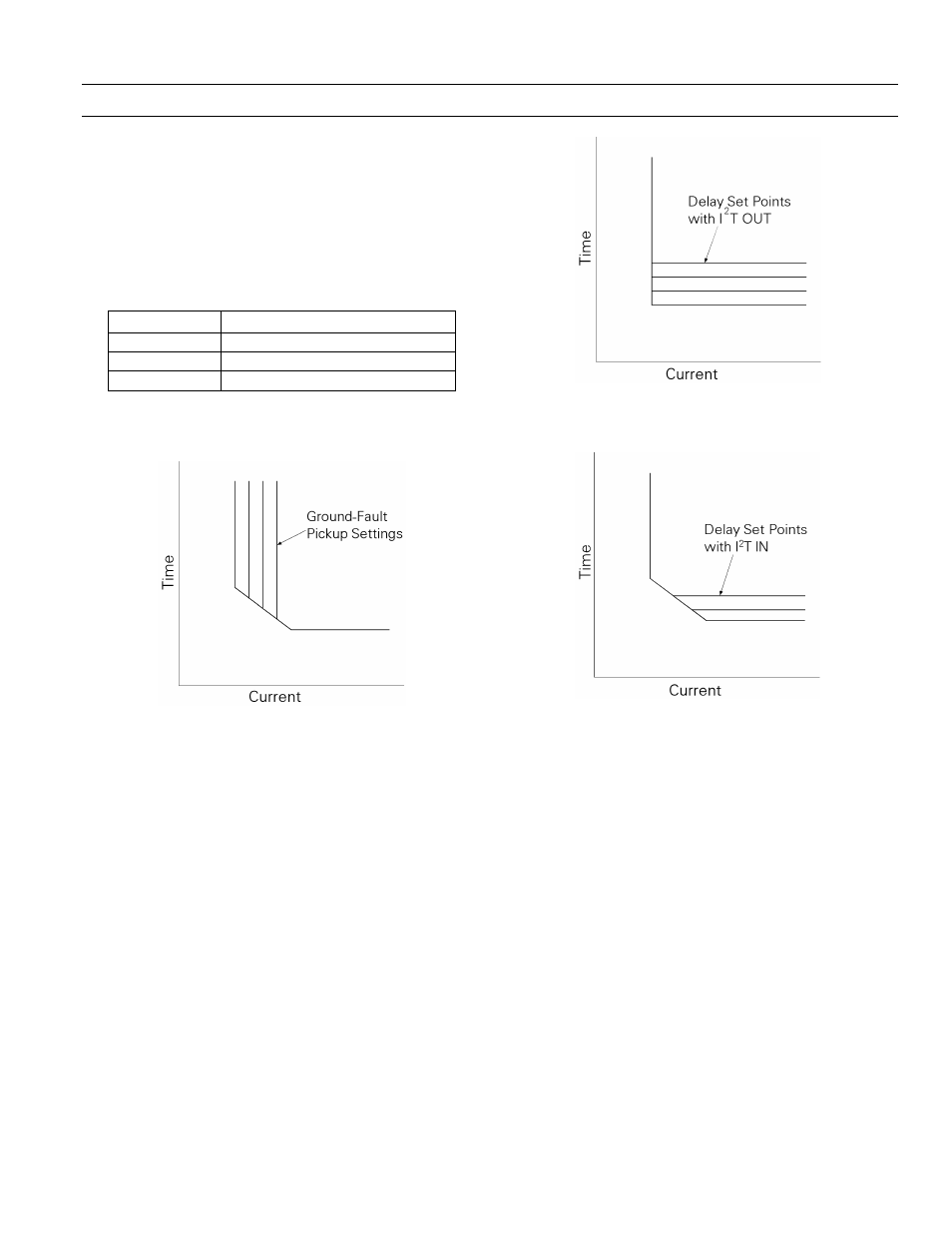
Figure 9. Time-current curve illustrating ground-fault pickup.
2–8 Ground-Fault Delay
This function sets the delay before the breaker trips when
the ground-fault pickup current is detected. The switch
settings
MIN
,
INT
, and
MAX
correspond to nominal time
delays of .10, .21, and .35 second, respectively. The delay
with
I
2
T OUT
is for the lower limit of each band. The delay
with
I
2
T IN
is at 200% of the pickup setting at the lower
limit of the band.
The
I
2
T OUT
function, illustrated in Figure 10, establishes
a constant time delay.
I
2
T IN
biases the delay with a
constant slope, as shown in Figure 11.
Figure 10. Time-current curve illustrating ground-fault delay with
I
2
T OUT.
Figure 11. Time-current curve illustrating ground-fault delay with
I
2
T IN.
2–9 Defeatable Ground Fault
All rating plugs have the additional setting
OFF
on the
Pickup switch, which defeats ground-fault protection.
These rating plugs are not UL listed.