Protrip™ trip units chapter 2. trip unit setup, 2–1 overview, 2–2 long-time pickup – GE Industrial Solutions ProTrip Trip Units for Low-Voltage User Manual
Page 11: 2–3 long-time delay
ProTrip™ Trip Units
Chapter 2. Trip Unit Setup
5
2–1 Overview
All of the Trip Unit protective functions are set with the
rotary selector switches on the front of the unit. Table 8
contains a summary of the functions and the available
settings.
Most of the selector switch scales (all but instantaneous
pickup) have a heavy curved line, with an arrowhead on
one end, connecting the low and high ends of the scale.
When the switch points anywhere within this region, the
highest value at the end of the line opposite the
arrowhead is the active setting.
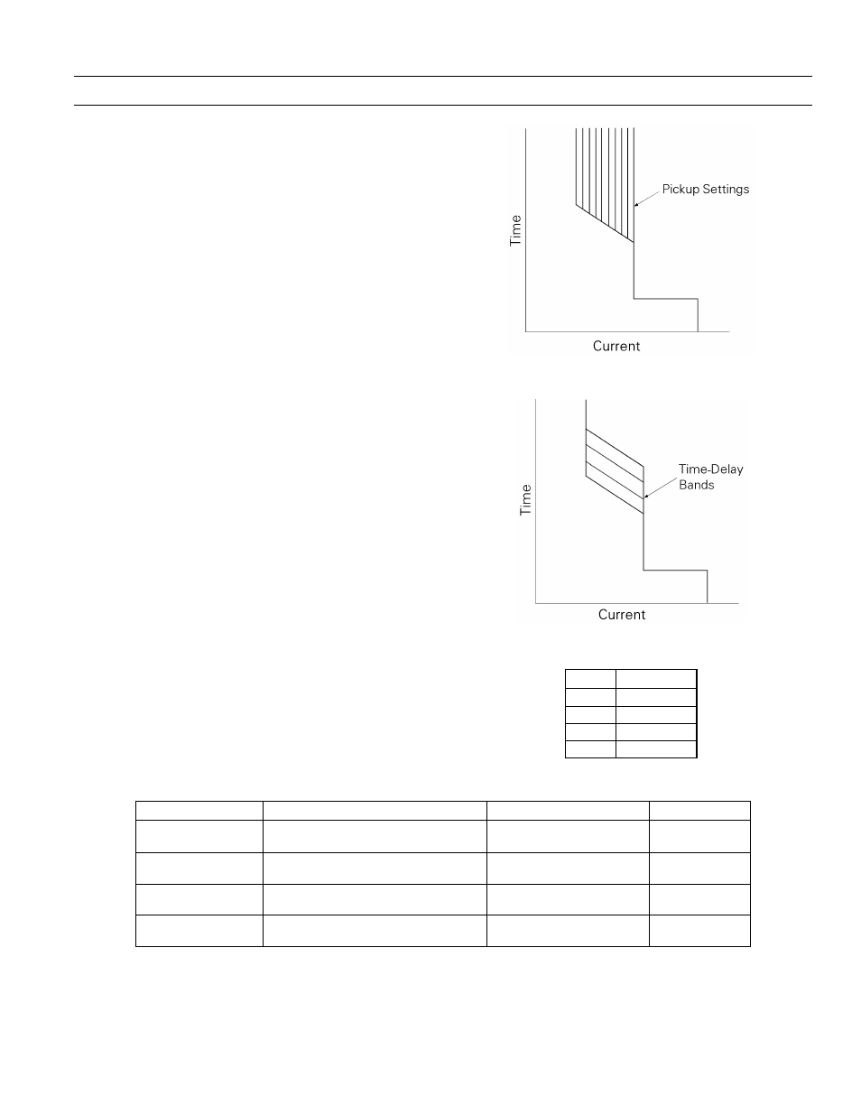
2–2 Long-Time Pickup
The long-time pickup set point establishes the breaker’s
nominal ampere rating, C, as a fraction of the rating plug
current, X. The choices for C are .5, .6, .7, .8, .9, .95, 1.0,
and 1.1 times X. Figure 3 illustrates the long-time pickup
settings.
2–3 Long-Time Delay
The long-time delay function allows normal momentary
overloads without nuisance tripping. The nominal time
delays at the lower limits of the bands for 600% of the
long-time current set point, C, for the four selectable
bands are listed in Table 9. Figure 4 illustrates the effect of
this delay on the trip time.
Figure 3. Time-current curve illustrating long-time pickup.
Figure 4. Time-current curve illustrating long-time delay.
Band
Delay, sec
1
2.4
2
4.9
3
9.8
4
20
Table 9. Nominal delays for the long-time delay bands.
Parameter
Pickup Settings
Delay Settings
Delay Curve
Long-Time Trip
.5, .6, .7, .8, .9, .95, 1.0, 1.1
multiple of Rating Plug Current (X)
2.4, 4.9, 9.8, 20 seconds
(Bands 1, 2, 3, 4)
Fixed
Short-Time Trip
1.5, 2, 2.5, 3, 4, 5, 7, 9
multiple of Long-Time setting (C)
.10, .21, .35 second
(Min, Int, Max)
I
2
T In, I
2
T Out
Instantaneous Trip
1.5, 2, 3, 5, 7, 9, 10
1
, 13
1
, 15
1
multiple of Rating Plug Current (X)
No delay
N/A
Ground-Fault Trip
.2, .25, .3, .35, .4, .45, .5, .6
multiple of Sensor rating (S)
2
.10, .21, .35 seconds
(Min, Int, Max)
I
2
T In, I
2
T Out
1
Maximum setting is limited by the frame size.
2
Maximum setting is limited to 1200 A. Pickup settings are determined by the breaker frame size
Table 8. Summary of protective functions and setting values for each.