GE Industrial Solutions EntelliGuard TU Conversion kits User Manual
Page 18
18
SECTION 7 Supplement to GEH-6466
For GE type AK-1-15, AK-1-25 Low Voltage Power Circuit Breakers.
Following text is in addition to Section 4 of GEH5964 after installing the communication harness
Routing the RELT wire harness
1. Route the RELT wire harness (set of 4 wires) along the top
surface of cubicle towards right as shown in figure 28.
2. Secure the wires with wire tie and apply caution label
supplied with kit on both breaker frame & compartment
door.
3. Mount the new Entelliguard
TU on front frame.
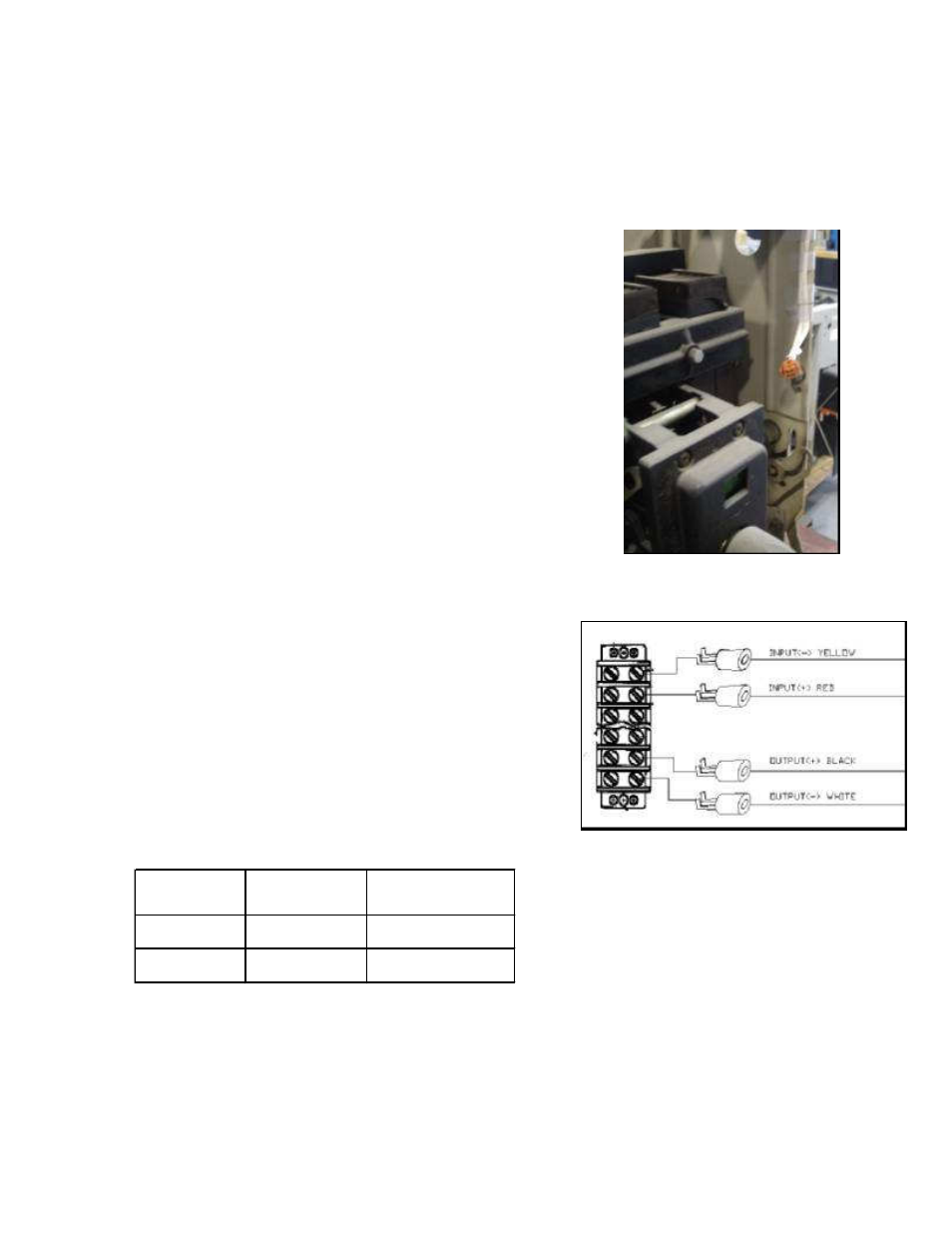
4. The other wire harness supplied loose with kit shall be
connected to the RELT wire harness to signal the input or
output.
5. The wires in harness are color coded for input
and output. Yellow and red wires are for input to
trip unit.
Black and white wires are for output from trip
unit.
6. If required to use the power supply harness for
control power supply, rout the 2-wire harness in
same way above RELT wire harness.
Individual wires in power supply harness are color coded
and numbered. The pins should be inserted at correct
places on backside of 36-pin connector. Refer table 12.
7. Refer Entelliguard
TU Installation manual DEH-
4567 for detailed description of input and output
signal requirements.
Figure 28
Figure 29
Wire Colour
Slot in 36 pin
connector
Function
Black
35
24 V DC Supply +
White
36
25 V DC Supply -
Table 11
-
+