Thermal considerations, Post solder cleaning and drying considerations – GE Industrial Solutions Austin SuperLynx SIP User Manual
Page 15
Data Sheet
October 2, 2009
Austin SuperLynx
TM
SIP Non-isolated Power Modules:
3.0 – 5.5Vdc Input; 0.75Vdc to 3.63Vdc Output; 16A output current
LINEAGE
POWER
15
Thermal Considerations
The power modules operate in a variety of thermal
environments; however, sufficient cooling should always
be provided to help ensure reliable operation.
Considerations include ambient temperature, airflow,
module power dissipation, and the need for increased
reliability. A reduction in the operating temperature of
the module will result in an increase in reliability. The
thermal data presented here is based on physical
measurements taken in a wind tunnel. The test set-up
is shown in Fig. 33. Note that the airflow is parallel to
the long axis of the module as shown in Fig. 34. The
derating data applies to airflow in either direction of the
module’s long axis.
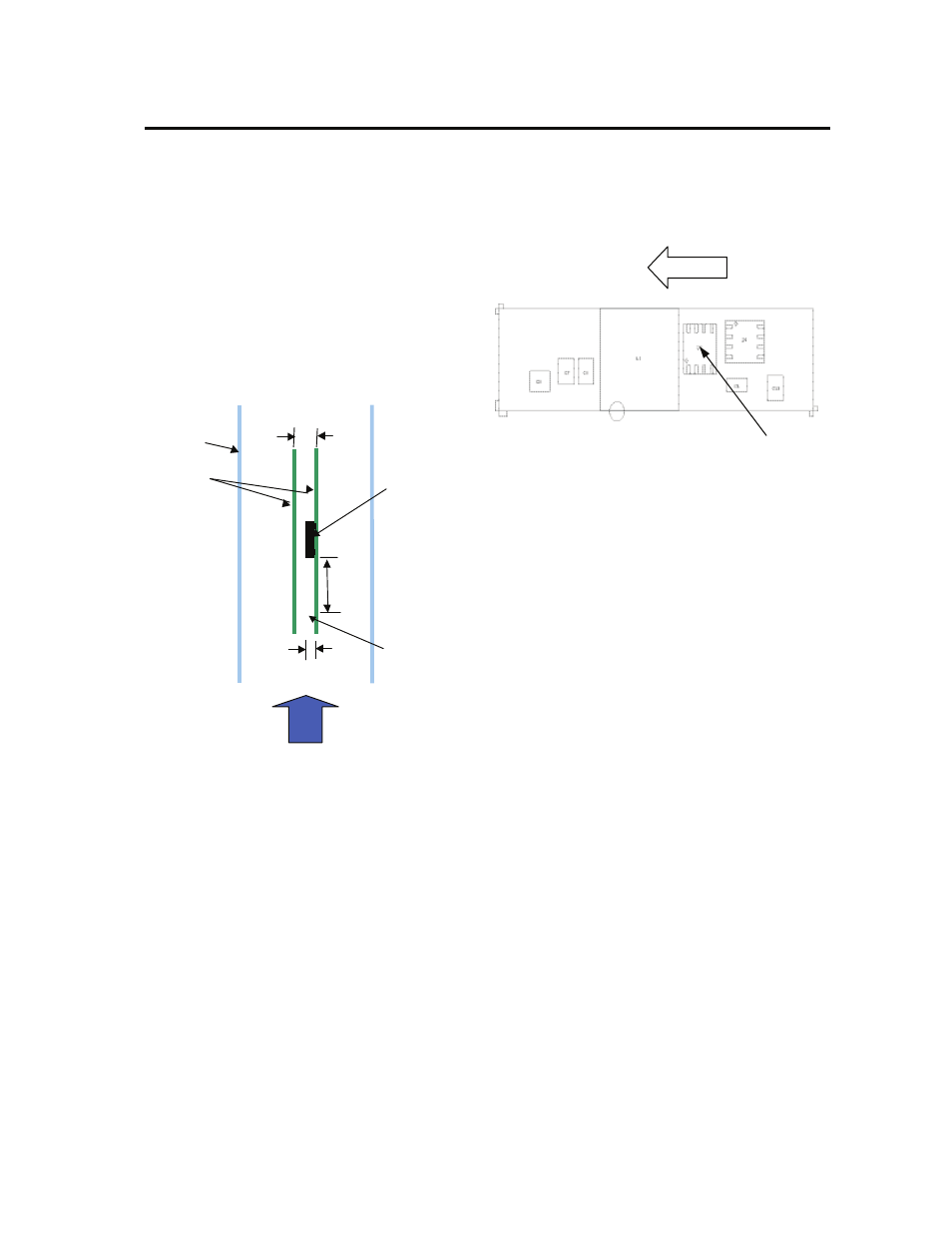
Figure 33. Thermal Test Set-up.
The thermal reference point, T
ref
used in the
specifications is shown in Figure 33. For reliable
operation this temperature should not exceed 115
o
C.
The output power of the module should not exceed the
rated power of the module (Vo,set x Io,max).
Please refer to the Application Note “Thermal
Characterization Process For Open-Frame Board-
Mounted Power Modules” for a detailed discussion of
thermal aspects including maximum device
temperatures.
Heat Transfer via Convection
Increased airflow over the module enhances the heat
transfer via convection. Thermal derating curves
showing the maximum output current that can be
delivered at different local ambient temperature (T
A
) for
airflow conditions ranging from natural convection and
up to 2m/s (400 ft./min) are shown in the Characteristics
Curves section.
Airflow
Tref
Top View
Figure 34. Tref Temperature measurement location
Post solder Cleaning and Drying
Considerations
Post solder cleaning is usually the final circuit-board
assembly process prior to electrical board testing. The
result of inadequate cleaning and drying can affect both
the reliability of a power module and the testability of the
finished circuit-board assembly. For guidance on
appropriate soldering, cleaning and drying procedures,
refer to Board Mounted Power Modules: Soldering and
Cleaning Application Note.
Through-Hole Lead-Free Soldering
Information
The RoHS-compliant through-hole products use the
SAC (Sn/Ag/Cu) Pb-free solder and RoHS-compliant
components. They are designed to be processed
through single or dual wave soldering machines. The
pins have an RoHS-compliant finish that is compatible
with both Pb and Pb-free wave soldering processes. A
maximum preheat rate of 3
°C/s is suggested. The wave
preheat process should be such that the temperature of
the power module board is kept below 210
°C. For Pb
solder, the recommended pot temperature is 260
°C,
while the Pb-free solder pot is 270
°C max. Not all
RoHS-compliant through-hole products can be
processed with paste-through-hole Pb or Pb-free reflow
process. If additional information is needed, please
consult with your Lineage Power technical
representative for more details.
Air
flow
x
Power Module
Wind Tunnel
PWBs
5.97_
(0.235)
76.2_
(3.0)
Probe Location
for measuring
airflow and
ambient
temperature
25.4_
(1.0)