Thermal considerations – GE Industrial Solutions ESTW025A0F Series User Manual
Page 9
Data Sheet
October 11, 2011
ESTW025A0F Series Eighth-Brick Power Modules
36–75Vdc Input; 3.3Vdc Output; 25A Output
LINEAGE
POWER
9
Thermal Considerations
The power modules operate in a variety of thermal
environments; however, sufficient cooling should be
provided to help ensure reliable operation.
Considerations include ambient temperature, airflow,
module power dissipation, and the need for increased
reliability. A reduction in the operating temperature of
the module will result in an increase in reliability. The
thermal data presented here is based on physical
measurements taken in a wind tunnel.
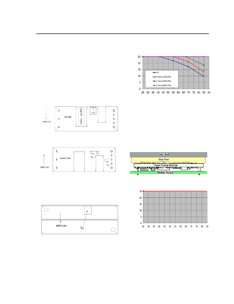
The thermal reference points, T
ref1
,T
ref2
and T
ref3
used
in the specifications for open frame modules are
shown in Figures 13a and 13b. For reliable operation
these temperatures should not exceed 125
o
C, 110
o
C
and 105
o
C respectively.
Figure 13a. T
ref 1
Temperature Measurement
Location for Open Frame Module.
Figure 13b. T
ref 2
and T
ref 3
Temperature
Measurement Locations for Open Frame Module.
The thermal reference point, T
ref
,
used in the
specifications for modules with heatplate is shown in
Figure 14. For reliable operation this temperature
should not exceed 110
o
C.
Figure 14. T
ref
Temperature Measurement
Location for Module with Heatplate.
Heat Transfer via Convection
Increased airflow over the module enhances the heat
transfer via convection. Derating curves, showing the
maximum output current that can be delivered by
each module versus local ambient temperature (T
A
)
for natural convection and up to 2.0 m/s (400 ft./min)
forced airflow, are shown in Figure 15.
O
U
TPU
T
CUR
RE
NT
, I
O
(A
)
AMBIENT TEMEPERATURE, T
A
(
o
C
)
Figure 15. Output Current Derating for the Open
Frame Module; Airflow in the Transverse Direction
from Vout(+) to Vout(-); Vin =48V.
Heat Transfer via Conduction
The module can also be used in a sealed environment
with cooling via conduction from the module’s top
surface through a gap pad material to a cold wall, as
shown in Figure 16. The output current derating
versus cold wall temperature, when using a gap pad
such as Bergquist GP2500S20, is shown in Figure 17.
Figure 16. Cold Wall Mounting
OUT
P
UT
C
URR
E
N
T, I
O
(A
)
COLDPLATE TEMEPERATURE, T
C
(
o
C)
Figure 17. Derated Output Current versus Cold
Wall Temperature with local ambient temperature
around module at 85C; Vin=48V.
Please refer to the Application Note “Thermal
Characterization Process For Open-Frame Board-
Mounted Power Modules” for a detailed discussion of
thermal aspects including maximum device
temperatures.