16v picotlynx, 4a: non-isolated dc-dc power modules, Data sheet – GE Industrial Solutions 16V PicoTLynx 4A User Manual
Page 19
GE
Data Sheet
16V PicoTLynx
TM
4A: Non-Isolated DC-DC Power Modules
8Vdc –16Vdc input; 0.6Vdc to 8.0Vdc output; 4A Output Current
September 10, 2013
©2013 General Electric Company. All rights reserved.
Page 19
Thermal Considerations
Power modules operate in a variety of thermal environments;
however, sufficient cooling should always be provided to help
ensure reliable operation.
Considerations include ambient temperature, airflow, module
power dissipation, and the need for increased reliability. A
reduction in the operating temperature of the module will
result in an increase in reliability. The thermal data presented
here is based on physical measurements taken in a wind
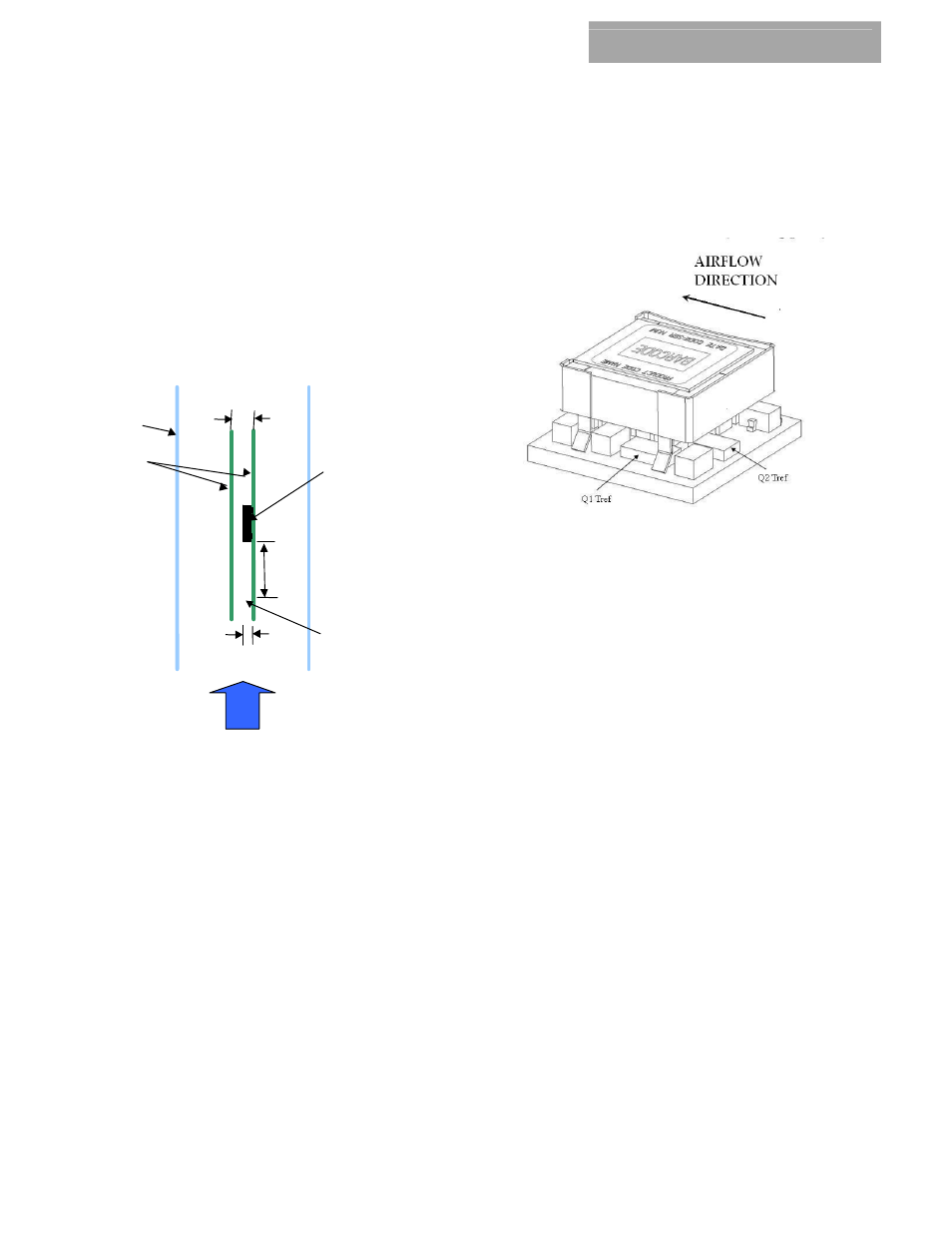
tunnel. The test set-up is shown in Figure 60. The preferred
airflow direction for the module is in Figure 61.
Air
flow
x
Power Module
Wind Tunnel
PWBs
12.7_
(0.50)
76.2_
(3.0)
Probe Location
for measuring
airflow and
ambient
temperature
25.4_
(1.0)
Figure 60. Thermal Test Setup.
The thermal reference points, T
ref
used in the specifications are
also shown in Figure 60. For reliable operation the
temperatures at these points should not exceed 120
o
C. The
output power of the module should not exceed the rated
power of the module (Vo,set x Io,max).
Please refer to the Application Note “Thermal Characterization
Process For Open-Frame Board-Mounted Power Modules” for a
detailed discussion of thermal aspects including maximum
device temperatures.
Figure 61. Preferred airflow direction and location of hot-
spot of the module (Tref).