16v picotlynx, 4a: non-isolated dc-dc power modules, Data sheet – GE Industrial Solutions 16V PicoTLynx 4A User Manual
Page 15: Safety considerations, Feature descriptions
GE
Data Sheet
16V PicoTLynx
TM
4A: Non-Isolated DC-DC Power Modules
8Vdc –16Vdc input; 0.6Vdc to 8.0Vdc output; 4A Output Current
September 10, 2013
©2013 General Electric Company. All rights reserved.
Page 15
0
10
20
30
40
50
60
70
80
90
100
0.5
2.5
4.5
6.5
Output Voltage(Volts)
Ri
p
p
le
(m
V
p
-p
)
1x10uF External Cap
1x47uF External Cap
2x47uF External Cap
4x47uF External Cap
Figure 53. Output ripple voltage for various output voltages
with external 1x10 µF, 1x47 µF, 2x47 µF or 4x47 µF ceramic
capacitors at the output (4A load). Input voltage is 12V.
Safety Considerations
For safety agency approval the power module must be
installed in compliance with the spacing and separation
requirements of the end-use safety agency standards, i.e., UL
60950-1, CSA C22.2 No. 60950-1-03, and VDE 0850:2001-12
(EN60950-1) Licensed.
For the converter output to be considered meeting the
requirements of safety extra-low voltage (SELV), the input must
meet SELV requirements. The power module has extra-low
voltage (ELV) outputs when all inputs are ELV.
The input to these units is to be provided with a fast-acting
fuse with a maximum rating of 6A in the positive input lead.
Feature Descriptions
Remote Enable
The 16V PicoTLynx
TM
4A power modules feature an On/Off pin
for remote On/Off operation. Two On/Off logic options are
available. In the Positive Logic On/Off option, (device code
suffix “4” – see Ordering Information), the module turns ON
during a logic High on the On/Off pin and turns OFF during a
logic Low. With the Negative Logic On/Off option, (no device
code suffix, see Ordering Information), the module turns OFF
during logic High and ON during logic Low. The On/Off signal
is always referenced to ground. For either On/Off logic option,
leaving the On/Off pin disconnected will turn the module ON
when input voltage is present.
For positive logic modules, the circuit configuration for using
the On/Off pin is shown in Figure 54.
1.5MEG
Q1
GND
ON/OFF
VIN+
_
+
PWM Enable
I
V
ON/OFF
MODULE
Rpullup
ON/OFF
2.05K
Figure 54. Circuit configuration for using positive On/Off
logic.
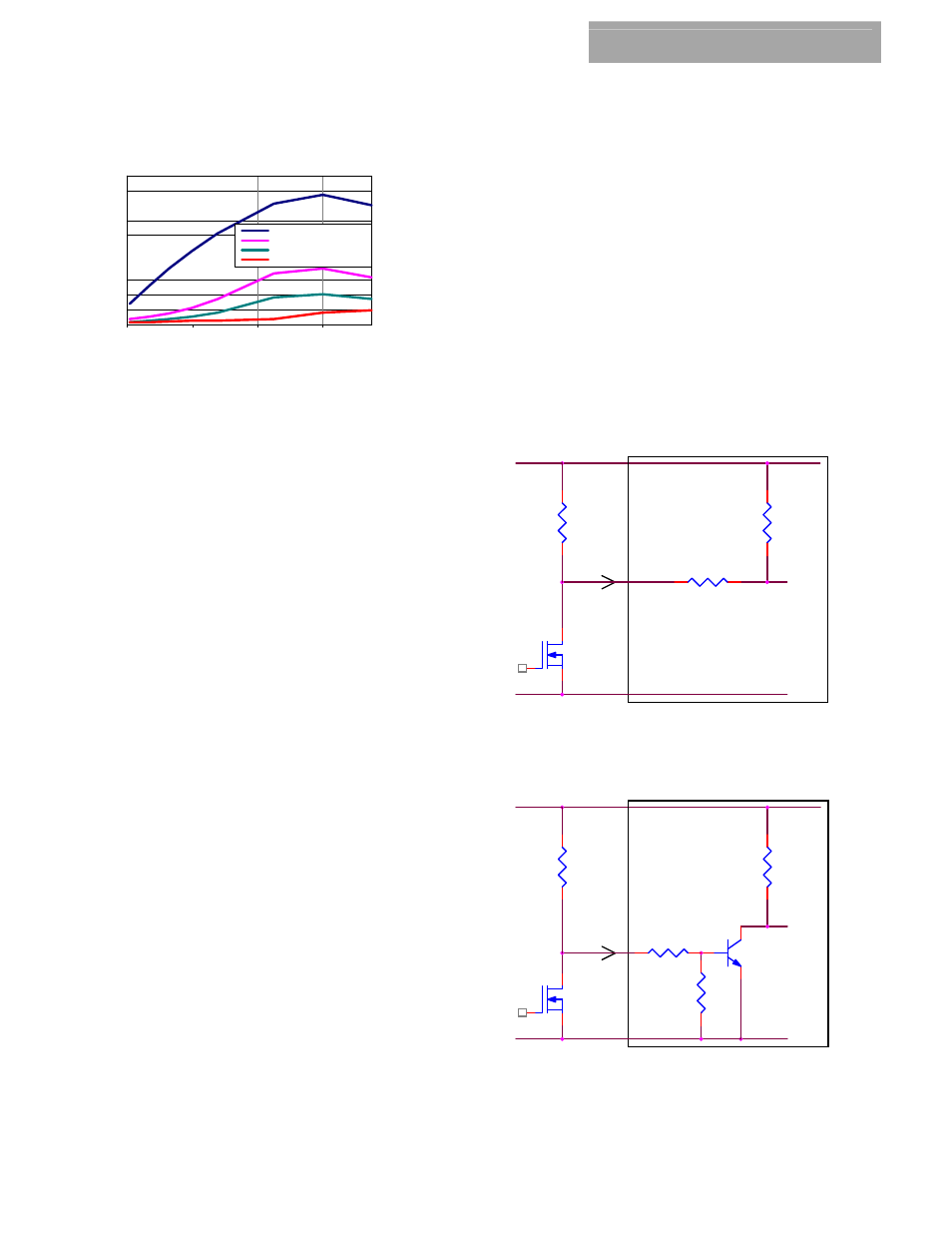
For negative logic On/Off modules, the circuit configuration is
shown in Fig. 55.
1.5MEG
Q2
VIN+
GND
+
PWM Enable
ON/OFF
ON/OFF
_
MODULE
I
V
Rpullup
ON/OFF
22K
Q1
22K
Figure 55. Circuit configuration for using negative On/Off
logic.