Geh-5626p2 – GE Industrial Solutions Spectra Series Power Panelboards AMC2FJ, AMC6FLS, AMC3FLS, AMC2FLS User Manual
Page 2
3. Install the circuit breaker.
a. Main devices (lugs only on ON side of circuit
breaker). Place the OFF side of the breaker over the
stud posts, as shown in Figure 4. Fasten the breaker
to the module with
1
/
4
-20 x
3
/
4
"
screws with conical
washers and #10-32 x 3
3
/
4
" screws with #10 flat
washers. After all screws are in place, tighten the
1
/
4
-20 screws to 40–50 in-lb and the #10-32 screws to
25–30 in-lb.
b. Branch devices (lugs only on OFF side of the
breaker). Remove the lug cover, if present. Place the
ON side of the breaker over the stud posts, as shown
in Figure 4. Secure the breaker to the module with
1
/
4
-20 x
3
/
4
"
screws with conical washers and #10-32
x 3
3
/
4
" screws with #10 flat washers.
Do not remove
the protective cap or tape from the top portion of
the stud posts unless a breaker is to be installed in
that position. After all screws are in place, tighten
the
1
/
4
-20 screws to 40–50 in-lb and the #10-32
screws to 25–30 in-lb. Replace the lug cover, if
present.
For double-branch devices, repeat this procedure
for the other breaker. Breaker types TFJ, TFK,
THFK, or TFL may be combined and breaker types
SFHA, SFLA, or SFPA may be combined.
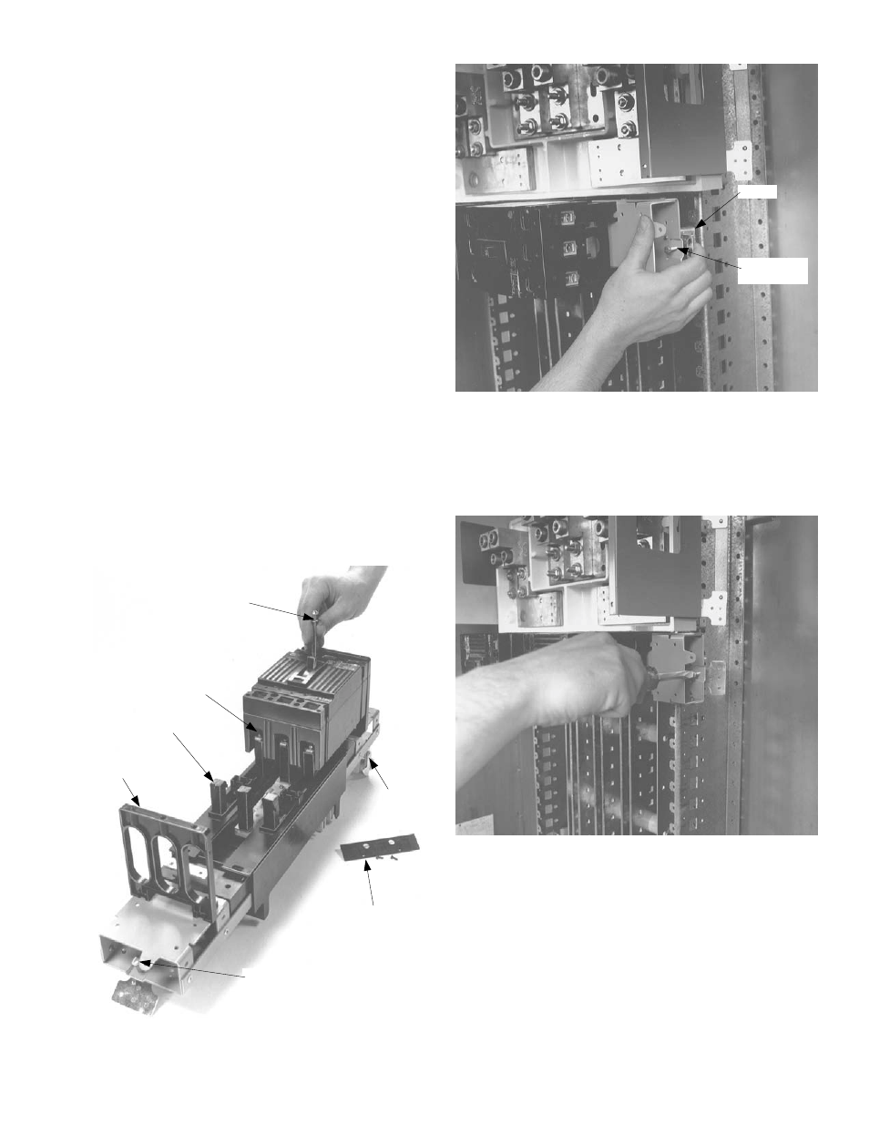
4. Position the breaker module. Loosen the latch lock
screws and fully retract the latches. Line up the guide
fingers on both ends of the module with the notches
in the panelboard interior rails, as shown in Figure 5.
Allow no space between units.
Figure 4. Installing the breaker on the module.
Figure 5. Positioning the breaker module.
5. Install the module. Latch one side of the circuit
breaker module. Release the rail latch. Pivot the
module onto the bus bars and engage the second
latch. Release the rail latch. Tighten the rail latch
screws to 25 in-lb, as shown in Figure 6.
Figure 6. Installing the breaker module.
6. Wire the circuits. Refer to the label on the circuit
breaker for the proper tightening torque.
7. Filler plate kits. Install the appropriate filler plate kits,
as listed in Table 1.
Lug
Cover
Stud
Post
1
/
4
-20 Screw &
Conical Washer
#10-32 Screw
& Flat Washer
Filler
Support
Latch Lock
Screw
Latch
Latch Lock
Screw
Latch