GE Industrial Solutions Spectra Series Power Panelboards AMC2FJ, AMC6FLS, AMC3FLS, AMC2FLS User Manual
Spectra series™ power panelboards, General, Installation
g
Spectra Series™ Power Panelboards
Circuit Breakers and Modules
WARNING:
Danger of electrical shock or injury.
Turn
OFF power ahead of the panelboard or
switchboard before working inside the
equipment or removing any component
.
Do
not remove circuit protective devices or any
other component until the power is turned
OFF.
General
These instructions apply to the following catalog numbers:
•Circuit breaker modules AMC6FJ, AMC4FJ, AMC3FJ,
AMC2FJ, AMC6FLS, AMC3FLS, AMC2FLS, and
AMC4FLS
•Circuit breaker frames TFJ, TFK, THFK, TFL, SFHA,
SFLA, and SFPA
Installation
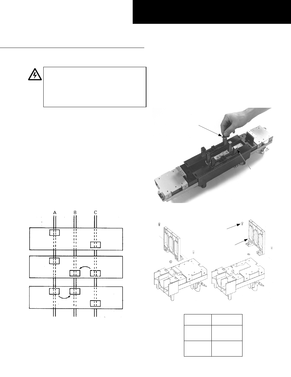
1. Phase balancing for two-pole devices in three-phase
systems.
To balance the panelboard load, remove the
screws on the appropriate bus clip, reposition the bus
clip as shown in Figure 1, then install and tighten the
screws to 27–32 in-lb.
Figure 1. Repositioning the bus clip to balance the load.
2. Prepare the breaker module.
Remove the protective
caps or insulating tape only from the tops of the stud
posts to which the circuit breaker is to be attached, as
shown in Figure 2. Fasten the filler supports, as shown
in Figure 3, with #10-32 x
3
/
4
" hex-head screws
tightened to 15–20 in-lb. The proper position of the
filler support is listed in Table 1.
Figure 2. Removing the caps or tape from the stud posts of the
breaker module.
Figure 3. Fastening the filler supports in position.
Breaker
Module
Filler Support
Position
AMC6FJ
AMC4FJ
AMC6FLS
4
AMC3FJ
AMC2FJ
AMC3FLS
1
Table 1. Filler support position per module type.
GEH5626 Installation Instructions
R04
A & C Phase
As Received
A & B Phase
B & C Phase
Protective Cap
or Insulating
Tape
Stud Post
Filler
Support
#10-32 x
3
/
4
"
Hex-Head
Screw