Thermal considerations, Heat transfer via convection – GE Industrial Solutions EVW020A0A Series (Eighth-Brick) User Manual
Page 9
Data Sheet
September 7, 2012
EVW020A0A Series Eighth-Brick Power Modules
36–75Vdc Input; 5.0Vdc Output; 20A Output Current
LINEAGE
POWER
9
Thermal Considerations
The power modules operate in a variety of thermal
environments; however, sufficient cooling should be
provided to help ensure reliable operation.
Considerations include ambient temperature, airflow,
module power dissipation, and the need for increased
reliability. A reduction in the operating temperature of
the module will result in an increase in reliability. The
thermal data presented here is based on physical
measurements taken in a wind tunnel.
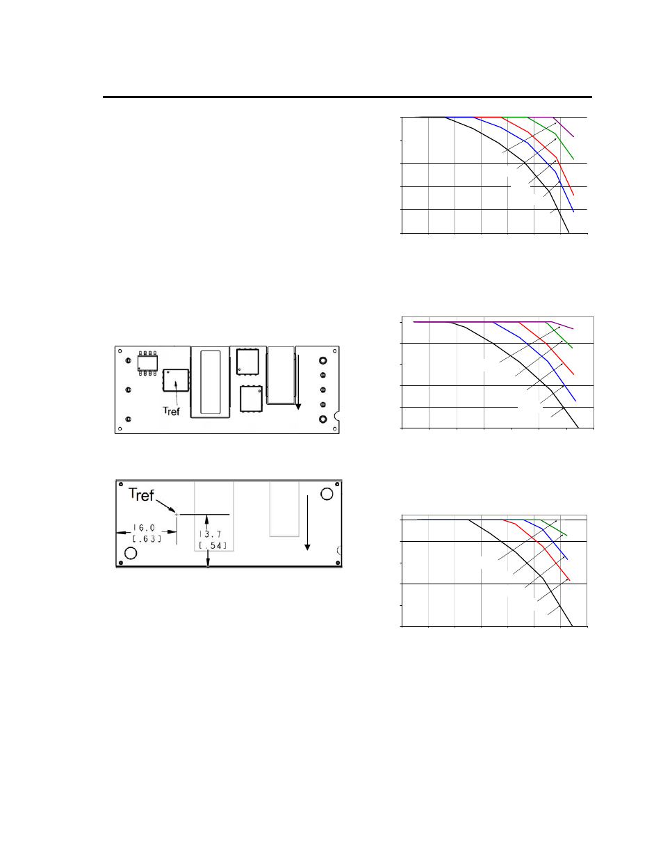
The thermal reference point, T
ref
used in the
specifications for open frame modules is shown in
Figure 13. For reliable operation this temperature
should not exceed 114
o
C.
The thermal reference point, T
ref
used in the
specifications for modules with heatplate is shown in
Figure 14. For reliable operation this temperature
should not exceed 105
o
C.
Figure 13. T
ref
Temperature Measurement
Location for Open Frame Module.
Figure 14. T
ref
Temperature Measurement
Location for Module with Heatplate.
Heat Transfer via Convection
Increased airflow over the module enhances the heat
transfer via convection. Derating curves showing the
maximum output current that can be delivered by
each module versus local ambient temperature (T
A
)
for natural convection and up to 3m/s (600 ft./min)
forced airflow are shown in Figure 14.
O
U
T
P
UT
CU
RRE
NT
, I
O
(A
)
0
4
8
12
16
20
20
30
40
50
60
70
80
90
1.0 m/s
(200 LM)
3.0 m/s
(600 LM)
2.0 m/s
(400 LM)
0.5 m/s
(100 LM)
NC
AMBIENT TEMEPERATURE, T
A
(
o
C
)
Figure 15. Output Current Derating for the Open
Frame Module; Airflow in the Transverse Direction
from Vout(+) to Vout(-); Vin =48V.
O
U
TPUT
CU
R
R
E
N
T
, I
O
(A
)
0
4
8
12
16
20
20
30
40
50
60
70
80
90
1.0 m/s
(200 LFM)
2.0 m/s
(400 LFM)
3.0 m/s
(600 LFM)
0.5 m/s
(100 LFM)
NC
AMBIENT TEMEPERATURE, T
A
(
o
C
)
Figure 16. Output Current Derating for the Module
with Heatplate; Airflow in the Transverse Direction
from Vout(+) to Vout(-); Vin =48V.
O
U
TPU
T
CUR
RE
NT
, I
O
(A
)
0
4
8
12
16
20
20
30
40
50
60
70
80
90
1.0 m/s
(200 LFM)
2.0 m/s
(400 LFM)
3.0 m/s
(600 LFM)
0.5 m/s
(100 LFM)
NC
AMBIENT TEMEPERATURE, T
A
(
o
C
)
Figure 17. Output Current Derating for the Module
with Heatplate and 0.25 in. heatsink; Airflow in the
Transverse Direction from Vout(+) to Vout(-); Vin
=48V.
AIRFLOW
AIRFLOW