GE Industrial Solutions EntelliGuard R AKD-8 User Manual
Page 30
29
EntelliGuard R Circuit Breaker Retrofill AKD-8 Installation Manual DEH-41549 02/12
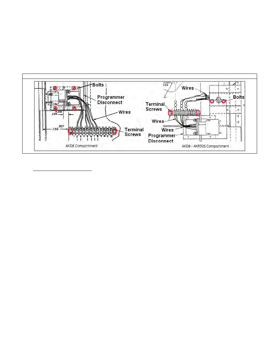
7. If the customer has chosen to install a 19-pin programmer disconnect assembly, replacing a 12-pin
programmer disconnect assembly, the terminal block mounted on the compartment needs to be
removed as well. This can be achieved by unfastening the two screws securing the terminal block with
the side wall of the compartment.
8. Unfasten the four bolts included that the that hold the programmer disconnect assembly on the wall of
the compartment to remove the compartment-side programmer disconnect assembly.
Figure 21. AKD-8—Loosen Hardware for the Programmer Disconnect Assembly
9. Install applicable programmer disconnect assembly on compartment and breaker.
• Wiring and completing task:
Install 19-pin programmer disconnect assembly on compartment and breaker:
1. Unpack the 19-pin programmer disconnect assembly from the box. Each box of the programmer
disconnect assemblies has a 20-pin terminal block supplied.
2. Check that the secondary disconnect plug assembly is not damaged and the wiring is intact.
3. Check that the programmer disconnect block is moving freely within the assembly and retracts to its
original position by spring-loading when it is slid back to the fully activated condition.
4. Check for electrical continuity between the contact pins on one and and the wire termination on the
other. Blocks containing faulty bullets should not be used for installation.
5. Install the new terminal block on the side wall of the the compartment and land the incoming wires from
the compartment to the terminal block. Any additional wires from the compartment side which
are
required for the 19-pin programmer need to be landed on the terminal block and checked for electrical
continuity.
6. Mount the programmer disconnect assembly on the side wall of the compartment where the original
programmer disconnect assembly was mounted.
7. Land the wires from the programmer disconnect to the terminal block mounted earlier.
8. Using a multimeter, check for continuity between the terminal block contact points to the corresponding
pins on the programmer disconnect. This should match against the wiring scheme planned for the new
19-pin programmer disconnect assembly on the compartment.