Accessory kit installation, Overload relays, Starter wiring diagram installation – GE Industrial Solutions CR454A Series Starters User Manual
Page 3
CR453A Accessories
Standard
Accessory
Contacts
(with quick connects on
C-2000
side-mount accessories) accessories
600V side-mount aux.
1NO-1NC
CR453XC611
BCLL11
contact block
2NO
CR453XC620
BCLL20
250V side-mount aux
1 SPDT
CR453XC211
—
contact block
2 SPDT
CR453XC222
—
600V front-mount aux.
1NO
BCLF10
BCLF10
contact block
1NC
BCLF01
BCLF01
Mechanical interlock,
side-mount
2NC CR453XM602 BEL02
Accessories
Check for Welded Contacts in Overload Relay
Disconnect power from device and control wiring from the
terminals of the relay. Connect the bell set or resistance-
measuring instrument across the relay terminals. Depress
and release the reset arm to ensure the relay is reset. In this
condition there should be continuity between the terminals.
In the tripped condition, the circuit between the terminals
should be open indicating the contacts are operating
normally. Remove the bell set or resistance measuring
apparatus, rewire the relay terminals and reset the relay for
normal operation.
For further technical details on overload relays, refer to
installation instructions GEH-6237A.
Accessory Kit Installation
Overload Relays
C
NC
N
C
NC
N
C
C
NC
N
NC
N
C
NC
N
NC
C
N
33
34 44
43
32 44
31 43
22
14
13
14
21
24
13 23
L1
L2
L3
T1
T2
T3
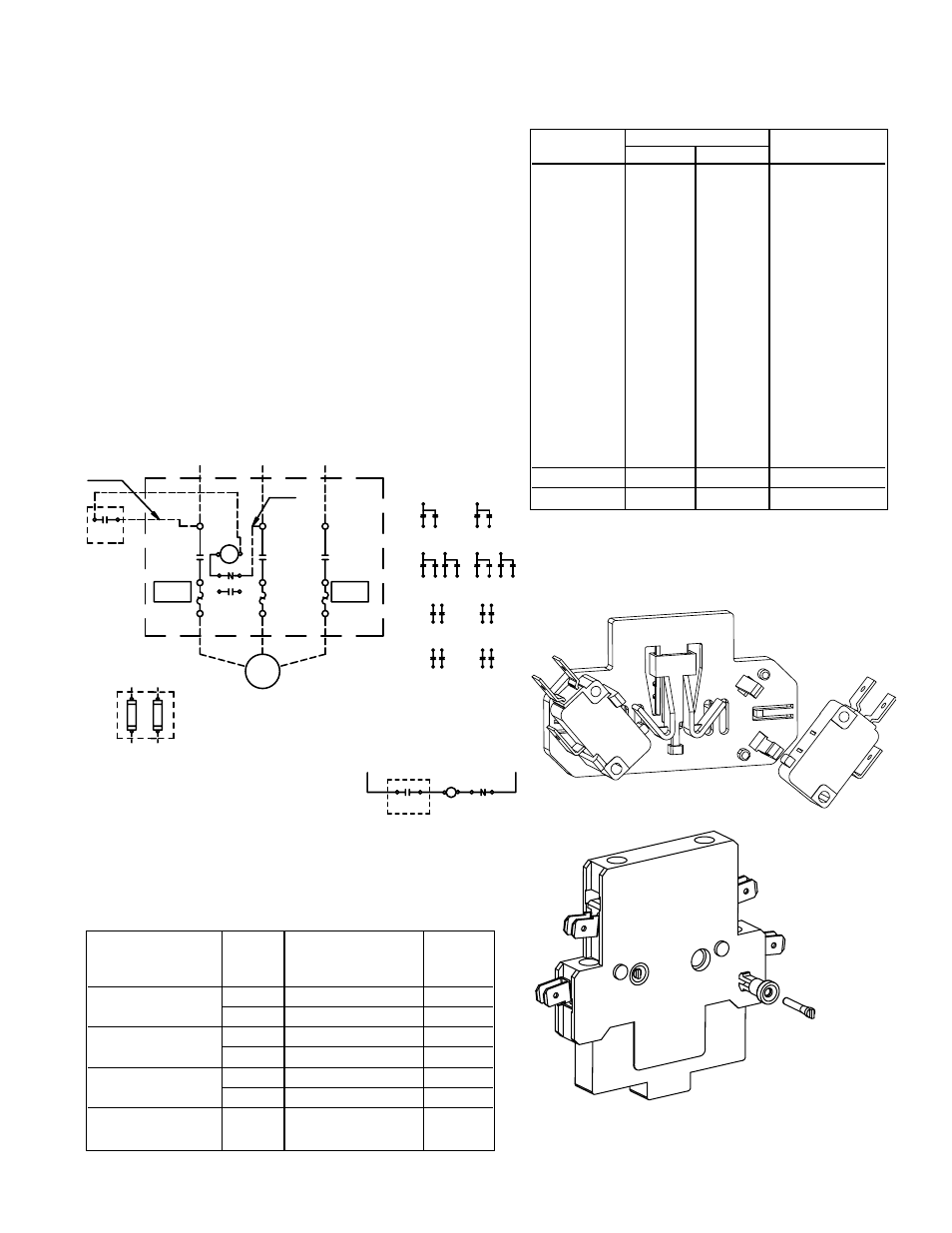
OPTIONAL
AUX
CONTACTS
OL-THERMAL OVERLOAD RELAY
NO-NORMALLY OPEN
NC-NORMALLY CLOSED
AUX CONTACT OPTONS
TYPE
LEFT
SIDE
RIGHT
SIDE
1 SPDT
2 SPDT
2 NO
1 NO-1 NC
M
OPTIONAL
AUX
CONTACTS
FRONT VIEW
MOTOR
M-LINE CONTACTOR
NOMENCLATURE
SPDT-SINGLE POLE DOUBLE THROW
ELEMENTARY
96
95
1
REMOTE
CONTROL
L1
L2
OL
M
CONTROL CIRCUIT FUSING
(IF USED)
L1
L2
1
96
NOTE: ADDITIONAL CONTROL CIRCUIT PROTECTION
MAY BE REQUIRED.PREFER TO NATIONAL
ELECTRIC CODE OR LOCAL CODES.
FOR SEPERATE CONTROL SOURCE-OMIT WIRES A AND B.
CONNECT CONTROL SOURCE TO 1 ON CONTROL DEVICE.
AND 96 ON OVERLOAD RELAY.
CONTROL
REMOTE
1
L1
L2
L3
95
96
97
98
WIRE B
WIRE A
Starter Wiring Diagram
Installation
Catalog No.
Current Range (A)
Contactor
Class 10
Class 20
RT1B
RT12B
0.16-0.26
RT1C
RT12C
0.25-0.41
RT1D
RT12D
0.4-0.65
RT1F
RT12F
0.65-1.1
RT1G
RT12G
1.0-1.5
RT1H
RT12H
1.3-1.9
RT1J
RT12J
1.8-2.7
CR453AB, RT1K
RT12K
2.5-4.1
AC, AD
RT1L
RT12L
4.0-6.3
RT1M
RT12M
5.5-8.5
RT1N
RT12N
8-12
RT1P
RT12P
10-16
RT1S
RT12S
14.5-18
RT1T
RT12T
17.5-22
RT1U
RT12U
21-26
CR453AC, AD
RT1V
RT12V
25-32
CR453AD
RT1W
RT12W
30-40
Typical 250V side auxiliary contact kit.
Typical 600V side auxiliary contact kit.