Contactor installation, Starter installation – GE Industrial Solutions CR454A Series Starters User Manual
Page 2
Contactor Installation
Before connecting to power supply:
1. Remove all packing.
2. Operate movable magnet and operating arm by
pressing down on the operating arm from the front
or side of the contactor to assure free movement.
3. Mount starter on a sturdy vertical support.
4. Make electrical connections as per wiring diagram.
For quick connect wiring, use UL recognized insulated
terminals.
Starter Installation
1. Remove all packing.
2. Motors with service factor of 1.15 or greater.
• Select overload relay as per the FLA shown in the
motor nameplate.
• Adjust the front mounted tripping current setting
dial to the motor FLA.
2. Motors with service factor less than 1.15
• Select overload relay as per the formula: Motor FLA
(shown in the motor plate) x 0.09.
• Adjust the front mounted tripping current setting dial
to the result of the above mentioned motor FLA.
3. Operate movable magnet and operating arm by pressing
down on the operating arm from the front or side of the
contactor to assure free movement.
4. Mount starter on a sturdy vertical support.
5. Make electrical connections as per wiring diagram.
For quick connect wiring, use UL recognized insulated
terminals.
6. Select the four modes by means of a front selector
lever.
7. Overload relays features tripping indicator, independent
& double break auxiliary tripping contacts (1NO+1NC)
with welding check lever.
8. Overload relay features thermal protection against
balanced overload, differential protection against
unbalanced overloads and also ambient temperature
compensation.
3.75
95,3
3.16
80,3
3.28
83,3
1.70
43,2
.35
8,9
MOUNTING HOLES FOR
#10 SCREWS(6 PLACES)
C
NC
N
C
NC
N
C
C
NC
N
NC
N
C
NC
N
NC
C
N
33
34 44
43
32 44
31 43
22
14
13
14
21
24
13 23
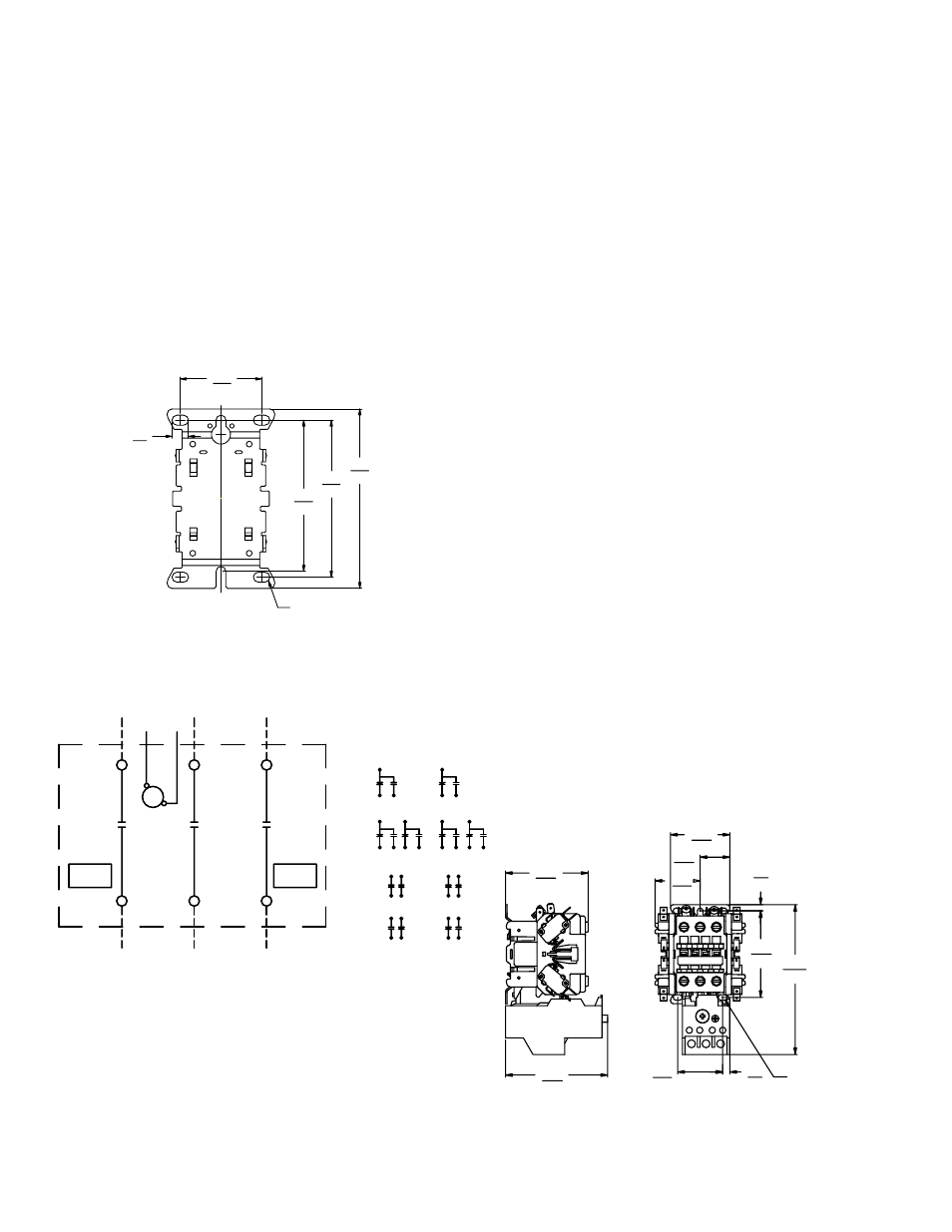
3 PHASE LINE CONNECTION
3 PHASE LINE CONNECTION
L1
L2
L2
T1
T2
T2
OPTIONAL
AUX
CONTACTS
NOMENCLATURE
M-LINE CONTACTOR
NO-NORMALLY OPEN
NC-NORMALLY CLOSED
AUX CONTACT OPTONS
TYPE
LEFT
SIDE
RIGHT
SIDE
1 SPDT
2 SPDT
2 NO
1 NO-1 NC
M
CONTROL
VOLTAGE
OPTIONAL
AUX
CONTACTS
FRONT VIEW
3.13
79,4
3.28
83,3
1.70
43,2
.24
6,0
2.25
57,0
1.71
43,3
3.87
98,2
5.68
144,3
.27
6,9
1.12
28,5
MOUNTING HOLES FOR
#10 SCREWS(6 PLACES)
Mounting Hole Dimensions
Contactor Wiring Diagram
CR454A Series Starter Dimensions