Car1248fp series rectifier, Data sheet, Control and status – GE Industrial Solutions CAR1248FP series User Manual
Page 7: Input: 90v, Output: 48v, Control signals, Status signals, Serial bus communications – car1248fpxc, Command code
GE
Data Sheet
CAR1248FP series rectifier
Input: 90V
AC
to 264V
AC
; Output: 48V
DC
@ 1200W; 5 V
DC
@ 0.5A
12 April 2012
©2012 General Electric Company. All rights reserved.
Page 7
Control and Status
Analog controls:
Details of analog controls are provided in
this data sheet under Signal Definitions.
Common ground:
All signals and outputs are referenced to
Output return. These include ‘Vstb return’ and ‘Signal return’.
Control Signals
Voltage programming (V
prog
):
An analog voltage on this signal
can vary the output voltage from 43.2V
DC
to 52.8V
DC
. The
equation of this signal is:
V
OUT
= 43.2 + 3.3 (V
prog
– 0.364) 0.364 < V
prog
< 3.27
If Vprog is ≥ 4V, or left open the programming signal is ignored
and the unit output is set at the setpoint of 48V
DC
.
Load share (Ishare):
Single wire analog signal between power
supplies connected in parallel. The Ishare pins should be tied
together for power supplies. No resistors or capacitors should
get connected to this pin.
Remote ON/OFF:
Controls the presence of the main 48V
DC
output voltage. This is an open collector, TTL level control
signal. Logic 1 turns ON the 48V
DC
output, while a Logic 0 turns
OFF the 48V
DC
output.
A turn OFF command either through this signal or firmware
commanded would turn OFF the 48V output.
Enable:
This is a short signal pin that controls the presence of
the 48V
DC
main output. This pin should be connected to
‘output return’ on the system side of the output connector. The
purpose of this pin is to ensure that the output turns ON after
engagement of the power blades and turns OFF prior to
disengagement of the power blades.
Write protect (WP):
This signal protects the contents of the
external EEPROM. When left open the EEPROM is write
protected. A LO permits writing to the EEPROM. This signal is
pulled HI internally by the power supply.
Status signals
Output current monitor (Imon):
A voltage level proportional to
the output current is present on this pin.
AC OK:
TTL compatible open collector. A (HI) on this signal
indicates that the input voltage is present within limits.
DC OK:
TTL compatible, open collector. A (HI) on this signal
indicates that the output voltage is present.
Over temp warning:
TTL compatible, open collector. A (HI) on
this signal indicates that temperatures are normal.
If an over temperature should occur, this signal changes to LO
for 10 seconds prior to shutdown. Unit restarts if internal
temperatures recover to normal operational levels.
Fault:
TTL compatible, open collector. A (HI) on this signal
indicates that no faults are present. This signal activates for
OTP, OVP, OCP, or AC fault.
PS Present:
Connected to ‘output return’. Its intent is to
indicate to the system that a power supply is present. This
signal may need to be pulled HI externally through a resistor.
Interrupt:
A TTL compatible status signal. Needs to be pulled
HI externally through a resistor. Open collector (HI) on this
signal indicates that no Interrupt has been triggered.
Serial Bus Communications – CAR1248FPxC
The I²C interface facilitates the monitoring and control of
various operating parameters within the unit and transmits
these on demand over an industry standard I²C Serial bus.
All signals are referenced to ‘Signal Return’.
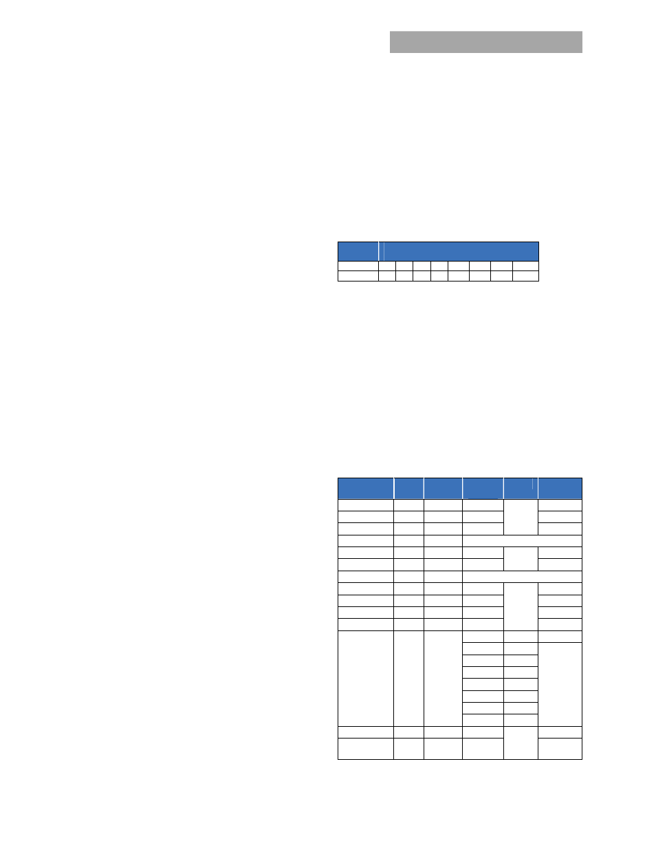
Device addressing:
The microcontroller (MCU) and the
EEPROM have the following addresses:
Device
Address Bit Assignments
(Most to Least Significant)
MCU
1 0 1 1 A2 A1 A0 R/W
EEPROM 1 0 1 0 A2 A1 A0 R/W
Address lines (A2, A1, A0):
Up to eight (8) modules to be
addressed on a single I²C bus. The pins are pulled HI internal
to the power supply. For a logic LO connect to ‘Output Return’
Serial Clock (SCL):
Host generated, this signal needs to be
pulled up externally ensuring that rise and fall time timing and
the maximum sink current is in compliance to the I²C
specification.
Serial Data (SDA):
This is a bi-directional line that needs to be
pulled up externally ensuring that rise and fall time timing and
the maximum sink current is in compliance to the I²C
specification.
Command code:
All registers are 16 bits, written as LSB followed by MSB.
All A/D’s are 10 bit (1024 steps). All constants can be fine-tuned
to compensate for manufacturing tolerances;
Name
CMD
Access
Default
/Name
Bits
Constant
V
OUT
00
R
48
0.102
I
OUT
01
R -
0.042
Temperature
02
R -
0.005
ON/OFF
03
R/W
1 – OFF, 0 – ON
Ilimit 04
R/W
28.6
0.042
Vset 05
R/W
48
0.094
Vprog 06
R
V
OUT
=43.2 + 3.3 (Vprog – 0.364)
OT trip
07
R/W
120
0.0049
OT recover
08
R/W
110
0.005
DC_OK_HI 09 R/W 67.5 0.102
DC_OK_LO 0A R/W 28.9 0.102
STATUS 0B R
Input 0 1-LL
AC_OK 1
1-normal
DC_OK 2
OT 3
Fault 4
Intrpt 5
OV 6
DC_INT 7
Firmware
0C
R
EEPROM 0D-
7C
R/W