Surface mount information, Continued), Tin lead soldering – GE Industrial Solutions EVW010A0B Series (Eighth-Brick) User Manual
Page 11: Lead free soldering, Pb-free reflow profile, Msl rating, Storage and handling, Post solder cleaning and drying considerations
Data Sheet
September 4, 2013
EVW010A0B Series Power Modules
36 – 75Vdc Input; 12.0Vdc Output; 10A Output Current
LINEAGE
POWER
11
Surface Mount Information
(continued)
technologies currently used in the industry. These
surface mount power modules can be reliably
soldered using natural forced convection, IR (radiant
infrared), or a combination of convection/IR.
The following instructions must be observed when
SMT soldering these units. Failure to observe these
instructions may result in the failure of or cause
damage to the modules, and can adversely affect
long-term reliability.
Tin Lead Soldering
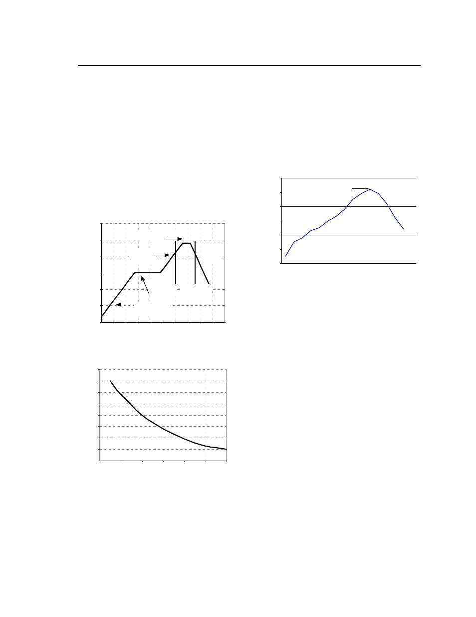
The recommended linear reflow profile using Sn/Pb
solder is shown in Figure 22 and 23. For reliable
soldering the solder reflow profile should be
established by accurately measuring the modules CP
connector temperatures.
R
E
FLO
W
TEMP (
C)
0
50
100
150
200
250
300
Preheat zo ne
max 4
o
Cs
-1
Soak zo ne
30-240s
Heat zone
max 4
o
Cs
-1
Peak Temp 235
o
C
Co oling
zone
1-4
o
Cs
-1
T
lim
above
205
o
C
REFLOW TIME (S)
Figure 22. Recommended Reflow Profile for
Tin/Lead (Sn/Pb) process.
M
A
X
T
E
M
P
SOLDER (
C)
200
205
210
215
220
225
230
235
240
0
10
20
30
40
50
60
Figure 23. Time Limit, T
lim
, Curve Above 205
o
C for
Tin/Lead (Sn/Pb) process.
Lead Free Soldering
The –Z version of the EVW010A0B modules are lead-
free (Pb-free) and RoHS compliant and are both
forward and backward compatible in a Pb-free and a
SnPb soldering process. Failure to observe the
instructions below may result in the failure of or cause
damage to the modules and can adversely affect
long-term reliability.
Pb-free Reflow Profile
Power Systems will comply with J-STD-020 Rev. C
(Moisture/Reflow Sensitivity Classification for
Nonhermetic Solid State Surface Mount Devices) for
both Pb-free solder profiles and MSL classification
procedures. This standard provides a recommended
forced-air-convection reflow profile based on the
volume and thickness of the package (table 4-2). The
suggested Pb-free solder paste is Sn/Ag/Cu (SAC).
The recommended linear reflow profile using
Sn/Ag/Cu solder is shown in Fig. 24.
Per J-STD-020 Rev. C
0
50
100
150
200
250
300
Reflow Time (Seconds)
R
efl
o
w
T
em
p
(°
C
)
He ating Zone
1°C/Second
Peak Temp 260°C
* Min. Time Above 235°C
15 Seconds
*Time Above 217°C
60 Seconds
Cooling
Zone
Figure 24. Recommended linear reflow profile
using Sn/Ag/Cu solder.
MSL Rating
The EVW010A0B modules have a MSL rating of 2A.
Storage and Handling
The recommended storage environment and handling
procedures for moisture-sensitive surface mount
packages is detailed in J-STD-033 Rev. A (Handling,
Packing, Shipping and Use of Moisture/Reflow
Sensitive Surface Mount Devices). Moisture barrier
bags (MBB) with desiccant are required for MSL
ratings of 2 or greater. These sealed packages
should not be broken until time of use. Once the
original package is broken, the floor life of the product
at conditions of
30°C and 60% relative humidity
varies according to the MSL rating (see J-STD-033A).
The shelf life for dry packed SMT packages will be a
minimum of 12 months from the bag seal date, when
stored at the following conditions: <40°C, < 90%
relative humidity.
Post Solder Cleaning and Drying
Considerations
Post solder cleaning is usually the final circuit-board
assembly process prior to electrical board testing. The
result of inadequate cleaning and drying can affect
both the reliability of a power module and the
testability of the finished circuit-board assembly. For
guidance on appropriate soldering, cleaning and
drying procedures, refer to Lineage Power Board
Mounted Power Modules: Soldering and Cleaning
Application Note (AN04-001).