Car1248tn series rectifier, Serial bus communications – car1248tn, Command code – GE Industrial Solutions CAR1248TN series User Manual
Page 5
GE
CAR1248TN series rectifier
Input: 90Vac to 264Vac; Output: -54Vdc @ 1200W
November 20, 2012
©2012 General Electric Company. All rights reserved.
Page 5
Serial Bus Communications – CAR1248TN
The I²C interface facilitates the monitoring and control of
various operating parameters within the unit and transmits
these on demand over an industry standard I²C Serial bus.
All signals are referenced to ‘Signal Return’.
Device addressing:
The microcontroller (MCU) and the
EEPROM have the following addresses:
Device
Address Bit Assignments
(Most to Least Significant)
MCU
1 0 1 1 A2 A1 A0 R/W
EEPROM 1 0 1 0 A2 A1 A0 R/W
Address lines (A2, A1, A0):
Up to eight (8) modules to be
addressed on a single I²C bus. The pins are pulled HI internal
to the power supply. For a logic LO connect to ‘Output Return’
Serial Clock (SCL):
Host generated, this signal needs to be
pulled up externally ensuring that rise and fall time timing and
the maximum sink current is in compliance to the I²C
specification.
Serial Data (SDA):
This is a bi-directional line that needs to be
pulled up externally ensuring that rise and fall time timing and
the maximum sink current is in compliance to the I²C
specification.
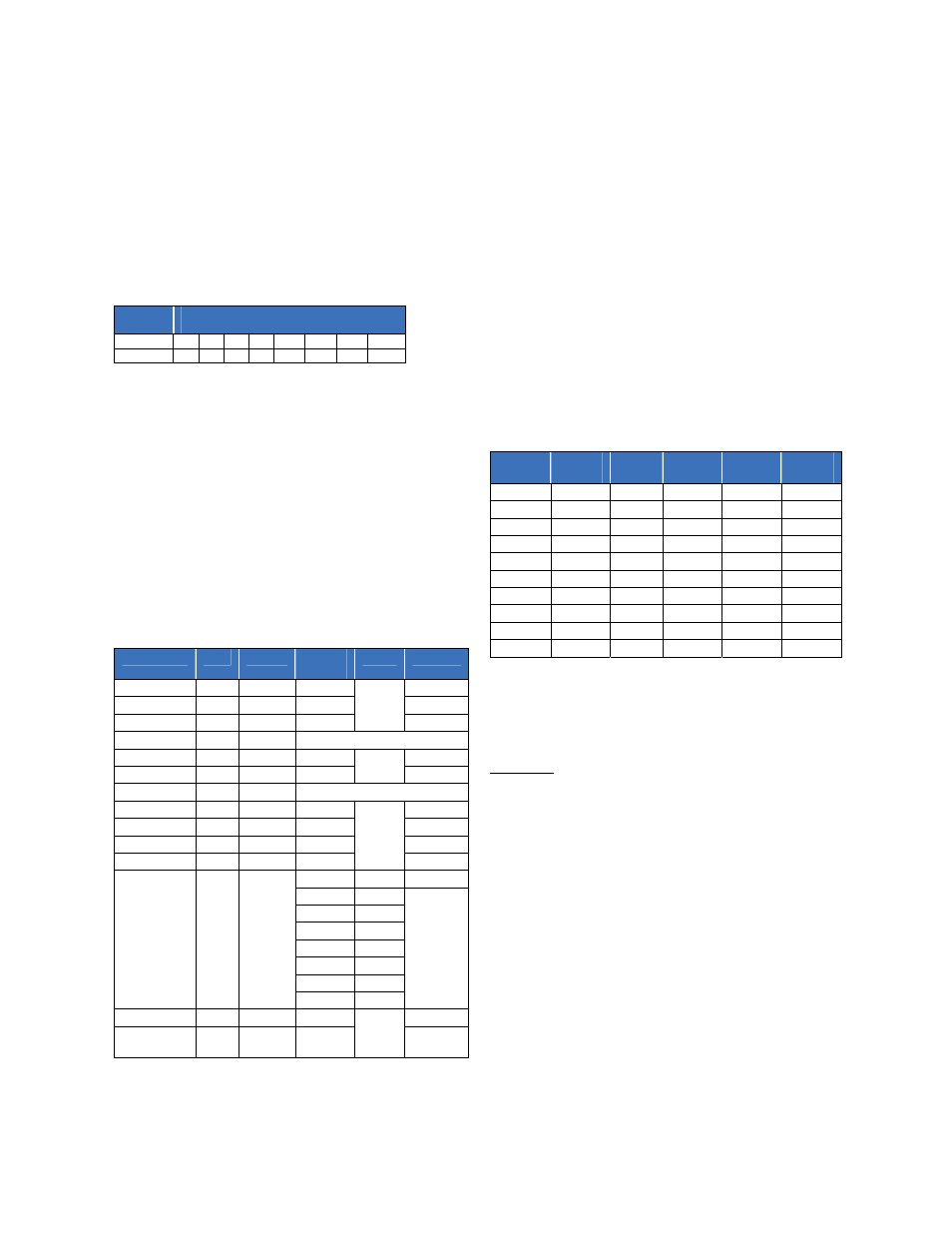
Command code:
All registers are 16 bits, written as LSB followed by MSB.
All A/D’s are 10 bit (1024 steps). All constants can be fine-tuned
to compensate for manufacturing tolerances;
Name
CMD
Access
Default
/Name
Bits
Constant
Vout 00
R
-54
0.102
Iout
01
R -
0.042
Temperature
02
R -
0.005
ON/OFF
03
R/W
1 – OFF, 0 – ON
Ilimit 04
R/W
25
0.042
Vset 05
R/W
-54
0.094
Vprog
06
R
Vout= 20 x Vprog
OT trip
07
R/W
120
0.005
OT recover
08
R/W
110
0.005
DC_OK_HI 09 R/W 55.6 0.102
DC_OK_LO 0A R/W 52.4 0.102
STATUS 0B R
Input 0 1-LL
AC_OK 1
1-normal
DC_OK 2
OT 3
Fault 4
Intrpt 5
OV 6
DC_INT 7
Firmware 0C R
EEPROM 0D-
7C
R/W
Vout [00]:
Output voltage read back, returns the voltage on
the anode side of the or’ing function, data LSB followed by
MSB.
The default value is -54Vdc
Example; readback 0211h, convert into its decimal equivalent
and then multiply by the constant, Vout = 529 x 0.102 =
54Vdc
Iout [01]:
Output current read back, data LSB followed by MSB.
Example; readback 021Fh, convert into its decimal equivalent
and multiply by the constant, Iout=543 x 0.042 = 22.8A
Temperature [02]:
Temperature read back, data LSB followed
by MSB.
Example; readback 037Bh, convert into its decimal equivalent
and multiply by the constant, temp = 891 x 0.005 = 4.36. In the
table below this corresponds to 25C
Data
Temp
C
Data
Temp
C
Data
Temp
C
4.83 -5 3.71 45 1.7 95
4.78 0 3.51
50 1.54 100
4.72 5 3.3 55 1.4 105
4.65 10 3.09 60 1.26 110
4.56 15 2.88 65 1.14 115
4.46 20 2.67 70 1.03 120
4.35 25 2.46 75 0.93 125
4.21 30 2.25 80 0.84 130
4.06 35 2.06 85
3.89 40 1.88 90
ON/OFF [03]:
A logic ‘1’ turns OFF the -54V output of the
power supply.
Ilim [04]:
This feature lowers the current limit from the default
values of 0253h (595), corresponding to 25A at high line and
01EFh (495) corresponding to 20.8A at low line.
The delivered output current cannot exceed the maximum
power capacity of the unit. At high line the power supply is
limited to 1200W, thus, at -48Vdc the output current is limited
to 25A.
Example: At high line, reduce the current limit to 20A.
Compute the data to be sent to the controller; 20 / 0.042 =
476. The hex equivalent of this decimal data is 01DCh. The
data should be sent across the bus as LSB [DC] followed by
MSB [01].
Vset [05]:
Changes the output voltage via i2c, if the Vprog
hardware signal is > 4Vdc. If the Vprog pin voltage level is <
4Vdc, this command is ignored.
The output voltage setting must be between -42 – -58Vdc.
The default value is 023Eh, corresponding to -54Vdc.
Example; set the output to 48Vdc. Compute the data to be
sent to the controller; 48 / 0.094 = 510. The hex equivalent of
this decimal data is 01FEh. The data should be sent across the
bus as LSB [FE] followed by MSB [01].