Figure 5 and figure 6, measure the, Turns), as illustrated in figure 6, Step 3 – install the circuit breaker – GE Industrial Solutions Record Plus Variable Depth Operating Mechanism: FE250 User Manual
Page 3
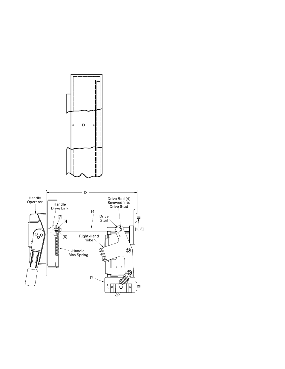
8. With the handle and mechanism in the
OFF
position,
place the small hole in the other end of the drive rod
[4] over the stud in the handle drive link.
9. Slide the drive pin [5] through the holes in the
handle drive link and the end of the drive rod [4].
Place a flat washer [6] over the end of the pin, then
slide the cotter pin [7] through the hole in the drive
pin [5], as illustrated in Figure 6. Do not bend the
cotter pin at this time, since slight movement of the
handle may be necessary to align the pin and hole.
Figure 5. Side view of enclosure, showing dimension D.
Figure 6. Installing the drive rod.
Step 3 – Install the Circuit
Breaker
This procedure is illustrated in Figure 7.
1. Move the STDA handle to the
ON
position. Be
careful to keep your hands away from the operating
mechanism while performing this installation.
2. Turn the circuit breaker to the
ON
position.
3. Install the circuit breaker on the operating
mechanism by inserting the four #8-32
x
2
7
/
8
" screws
[8] and lock washers [9] into the mounting holes in
the breaker and into the corresponding tapped holes
in the mechanism, as illustrated in Figure 7.
4. Place the yoke top plate [10] on the left and right
yoke plates with the breaker handle fitting through
the cutout in the top plate. Secure with four #8-32
x
1
/
4
" screws [11] and lock washers [9] into the tapped
holes in the yoke side plates.
5. Attempt to turn the breaker
OFF
with the STDA
handle. If the breaker does not move to the
OFF
position, disconnect the drive rod [4] from the
handle and thread the rod one turn further
(clockwise) into the drive stud. Reattach the drive
rod to the handle mechanism. Repeat until the
breaker turns
OFF
with the handle mechanism.
6. Attempt to turn the breaker
ON
with the handle
mechanism. If the breaker does not turn
ON
, repeat
the adjustment of step 5 until moving the handle
ON
also turns the breaker
ON
.
7. With the breaker in the
ON
position, use the TRIP
button to open the breaker. Attempt to reset the
breaker by moving the handle to the
OFF
(reset)
position. If the breaker is
RESET
, it can be turned
ON
and
OFF
. If the breaker will not reset, repeat the
adjustment of step 5 until the breaker resets.
8. When the
ON
,
OFF
, and
RESET
positions are working
properly with the handle mechanism, bend the legs
of the cotter pin [7] to secure the drive rod [4] in
place.
9. Attach the handle bias spring, illustrated in Figure 6,
included with the STDA handle mechanism kit.
10. Tighten all #8-32 screws to 20–25 in-lb and
1
/
4
-20
screws to 45–50 in-lb.
11. Complete the circuit breaker installation according
to DEH40463, the installation instructions supplied
with the breaker.