Step 1 – unpack and inspect, Step 2 – install the operating mechanism – GE Industrial Solutions Record Plus Variable Depth Operating Mechanism: FE250 User Manual
Page 2
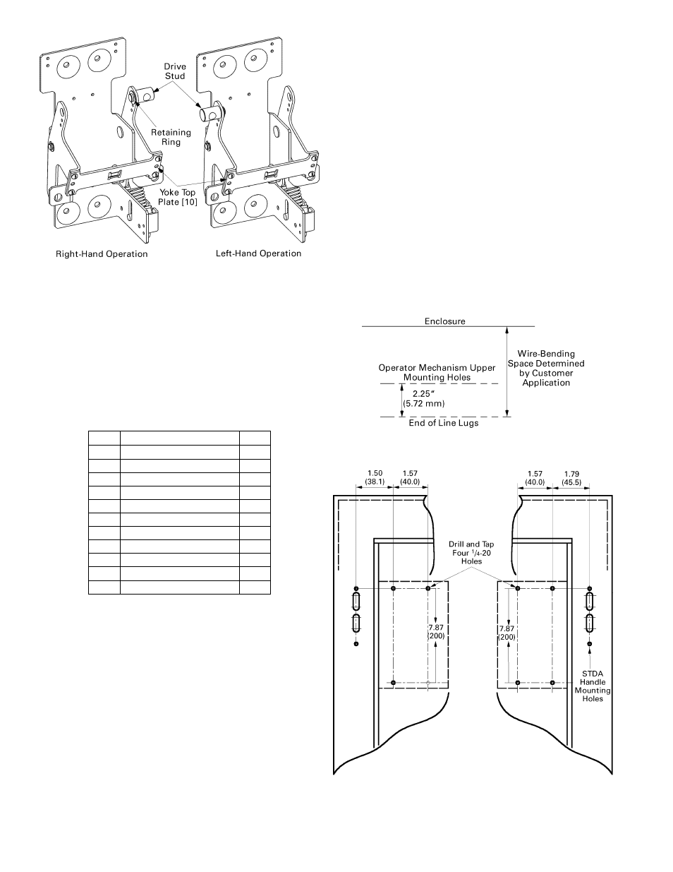
Figure 2. Variable-depth operating mechanism, as set up for right-
hand or left-hand operation.
Step 1 – Unpack and Inspect
Unpack the variable-depth operating mechanism kit and
drive rod kit(s) and inspect the parts for any shipping
damage. Verify that all parts are supplied, as listed in
Table 1.
Note that the numbers in brackets in the following figures
and installation instructions refer to the item numbers in
this table.
Item Description
Qty.
1 Operating
mechanism 1
2 Screw,
1
/
4
-20 x
7
/
16
" 4
3 Lock
washer,
1
/
4
" 4
4 Drive
rod
1
5 Drive
pin
1
6 Flat
washer
1
7 Cotter
pin
1
8
Screw, #8-32 x 2
7
/
8
" 4
9 Lock
washer,
#8
8
10 Yoke top plate
1
11 Screw,
#8-32
x
1
/
4
" 4
Table 1. Parts included in the variable-depth operating mechanism kit,
catalog number FCNFM.
Step 2 – Install the Operating
Mechanism
1. If the operating mechanism is to be installed with
right-hand operation, proceed to step 2. If it is to be
installed for left-hand operation, remove the
retaining ring and drive stud from the right-hand
yoke, as shown in Figure 2, and reinstall them on the
left-hand yoke.
2. The required wire-bending space between the
breaker line lugs and the enclosure end wall is shown
in Figure 3. Use this to determine the operating
mechanism mounting location.
3. Drill and tap four
1
/
4
-20 holes in the enclosure
subplate for mounting the operating mechanism, as
shown in Figure 4. Dimensions for mounting for
both left- and right-hand operation are also shown in
4. Install the type STDA flange-mounted handle
mechanism, as described in the instructions
accompanying the kit (GEH5314).
5. Secure the operating mechanism [1] to the tapped
holes in the enclosure subplate with the four supplied
1
/
4
-20
x
7
/
16
" screws [2] and lock washers [3].
6. As shown in Figure 5 and Figure 6, measure the
dimension D, which is the distance from the handle-
mounting surface to the operating mechanism
mounting surface. Cut the drive rod [4] overall
length 2
1
/
2
" shorter than the D dimension. The
minimum D distance is 6.5" (165 mm).
7. Screw the drive rod [4] into the drive stud on the
operating mechanism until it is flush with the
opposite side of the stud (approximately 10 full
turns), as illustrated in Figure 6.
Figure 3. Wire-bending space between the breaker line lugs and the
enclosure end wall.
Figure 4. Mounting pattern for the operating mechanism.