Monitor controls – Universal Audio Apollo Software User Manual
Page 52
Apollo Software Manual
Chapter 3: Console Application
52
Monitor Controls
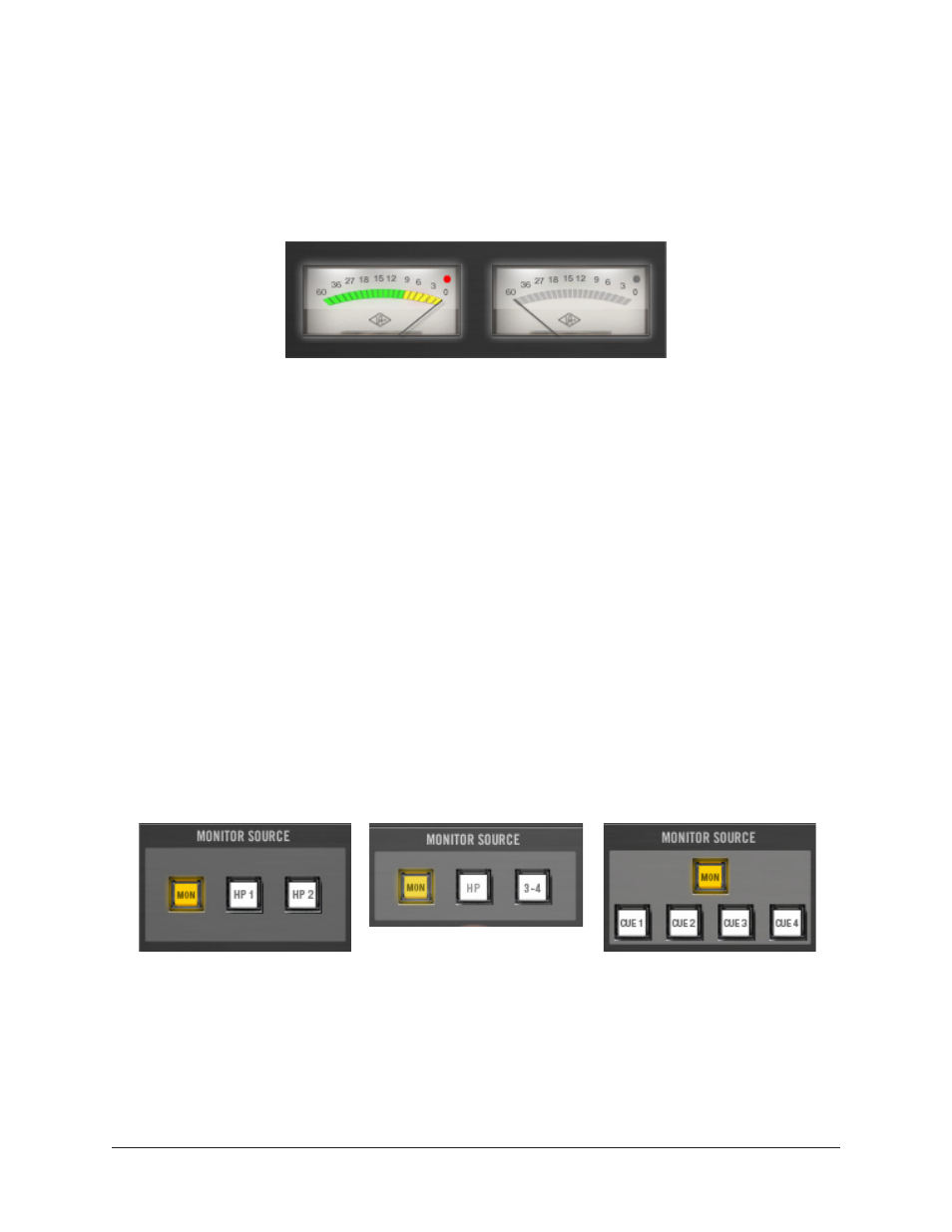
Monitor Meters
Console’s Monitor Meters are twin pin-style peak meters that display the pre-fader signal
levels of Apollo’s monitor mix bus. Levels displayed here reflect the state of the Monitor
1 – 2 LED meters on Apollo’s front panel.
Console’s Monitor Meters
Meter Source
When the monitor output signals are changed with the
displayed here reflect the changed monitor outputs source signal.
Meter Level Scale
The meter numbering represents the digital level of the monitor channel, where “0” is 0
dBFS. Both meters include a clip LED that illuminates when the level at the monitor out-
puts exceed 0 dBFS (when D/A converter clips). The clip LED hold time can be adjusted
in the
.
Important:
If clipping occurs, reduce the monitor output levels by reducing levels
of the channels feeding the monitor mix bus to eliminate undesirable D/A clipping
distortion.
Monitor Source
The Source buttons define which signal bus is routed to the Apollo’s monitor outputs.
The active monitor source is indicated by a yellow button.
The monitor source buttons with Apollo (left), Apollo Twin (center), and Apollo 16 (right).