Caution, Destruction of the control unit and other devices – OSRAM OPTOTRONIC OT EASY 60 II User Manual
Page 11
11
OT EASY 60
IV 2009
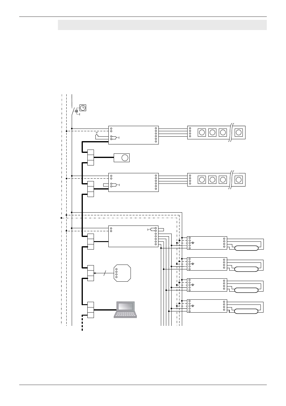
Installation
Wiring diagram (example of a master-slave circuit)
CAUTION!
Destruction of the control unit and other devices!
•
Master-slave connection lines conduct protective extra-low voltage signals; do
not route together with power supply or LED lines.
•
Ensure that the master-slave connection lines are sufficiently insulated against
the power supply or lamp lines.
OT EASY 60
OT EASY 60
Master
Slave
4
DALI EASY
Slave
PE N L
Y-connector
Y-connector
Y-connector
Y-connector
Y-connector
Easy signal
24 V (+)
CH1 (R-)
CH2 (G-)
CH3 (B-)
CH4 (W-)
GND (-)
+
R
G
B
L
N
Easy signal
24 V (+)
CH1 (R-)
CH2 (G-)
CH3 (B-)
CH4 (W-)
GND (-)
+
R
G
B
L
N
~
~
DA
DA
Easy signal
GND (-)
CH4+ (W)
CH3+ (B)
CH2+ (G)
CH1+ (R)
L
N
~
~
DA
DA
~
~
DA
DA
~
~
DA
DA
Power switch and/or
timer switch (optional)
Infrared receiver or
additional EASY components
External
switch
DALI ECG
Red bulb
LINEARlight Colormix LED module
Pushbutton coupler or
additional EASY components
White bulb
Blue bulb
Green bulb
EASY PC Kit or
additional EASY components
Max. total
line length 100 m
DALI ECG
DALI ECG
DALI ECG
LINEARlight Colormix LED module