Ocean Optics LIBS2500plus User Manual
Page 24
2: Installing the LIBS System
14
166-00000-000-02-0110
Laser Connection
Spectrometer
Connection
Function
Lamp Sync
LAMP SYNC
This cable is connected to the laser’s strobe
synchronization output. It tells the spectrometer
the exact time the strobe is firing. If such a line
is not available, connect this to the Laser
Trigger OUT cable using a BNC tee.
Ext Q-Sw
EXT Q SWITCH
This cable connects to the external Q-switch of
the laser. It fires the Q-switch under software
control. Most lasers have a switch that must be
set to allow this to happen. If only an external
trigger input is available, you do not need to use
this line, but you will have no control over the Q-
switch event.
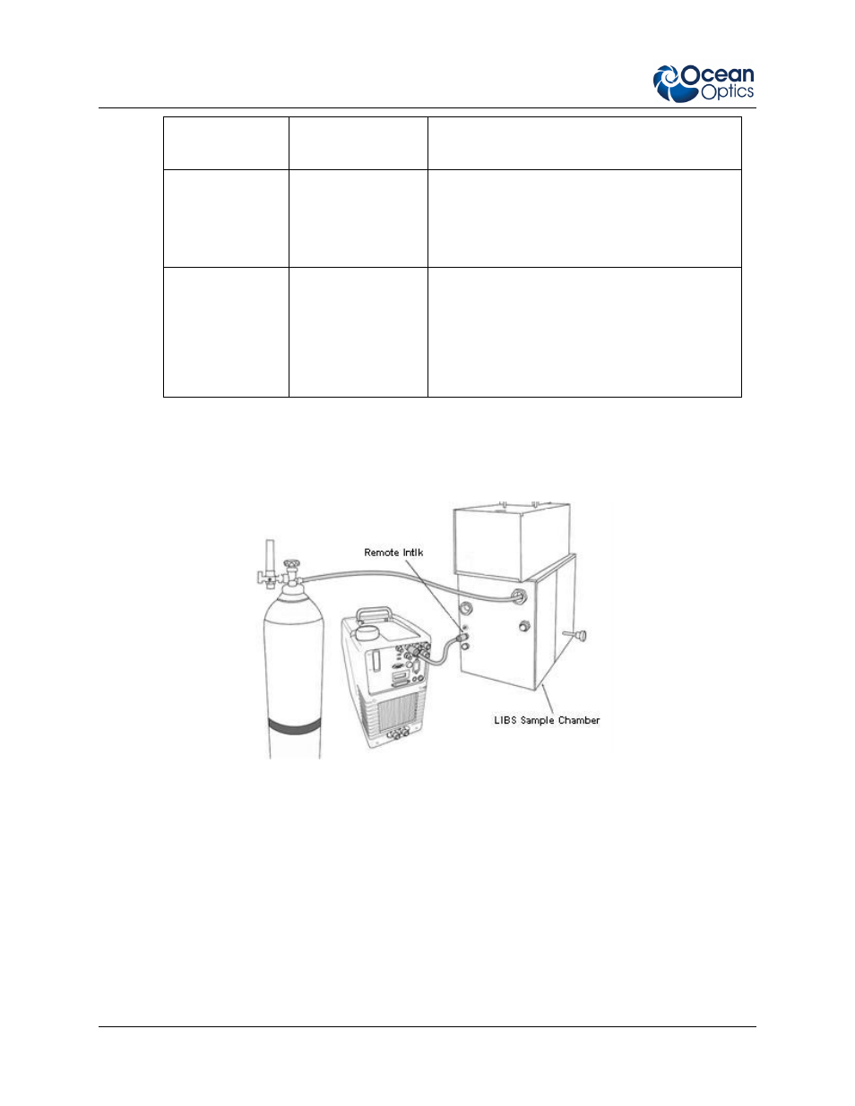
7. Connect one end of the BNC cable to the LIBS Sample Chamber. Remove the cap from the
Remote Interlock (Remote Intlk) connector on the back of the laser power supply and attach the
other end of the BNC cable.
Connecting the LIBS Sample Chamber to the Laser Power Supply and Inert Gas
8. Install the fiber optic assembly in the Sample Chamber and roughly align.
9. Ensure that the switches on the rear of the laser power supply are set for external triggering.
10.
If you intend to use inert gas in your set-up, connect the gas tank to the LIBS Sample Chamber.