Ocean Optics LIBS2500plus User Manual
Page 23
2: Installing the LIBS System
166-00000-000-02-0110
13
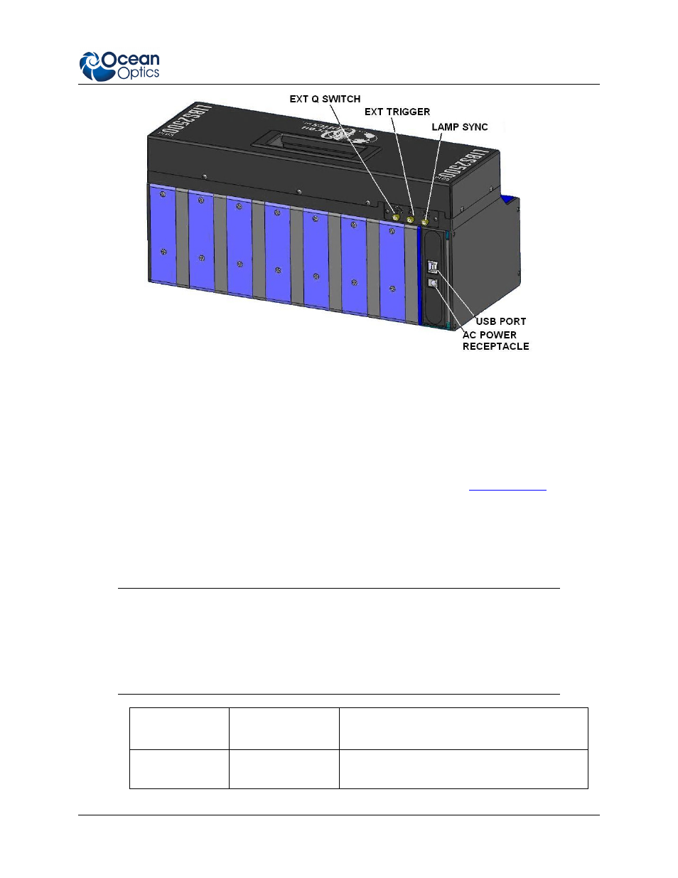
Rear Panel of 7-Channel Spectrometer Rack
2. Plug the USB cable into the USB port on the rear of the spectrometer rack, then into the PC’s
USB port. The computer’s operating system will recognize the new hardware and load the
appropriate drivers for each of the spectrometers in the LIBS system.
3. Connect the fiber from the rear of the Sample Chamber or Crossfire system to each spectrometer
channel’s SMA connector on the front of the spectrometer rack.
4. Start the OOILIBSplus software and configure your spectrometers (see
5. Attach the laser cables from the laser to the laser power supply. See your laser’s documentation
for specific instructions.
6. Using the supplied BNC cables, attach them to the connectors on the back of the laser power
supply, then connect them to the rear panel of the spectrometer rack as described in the following
table.
Caution
Beware of lasers that use negative logic and/or high voltage outputs. Lamp Sync
signals as high as 33 volts have been observed in testing, and the electronics in the
LIBS2500plus may not survive pulse voltages of this intensity. The spectrometer
electronics are designed to drive the 50ohm loads normally associated with BNC
connectors, and all signals are 5V TTL.
Laser Connection
Spectrometer
Connection
Function
Ext Trig
EXT TRIG
This cable is connected to the external trigger
connection of the laser. It initiates a laser fire.