H-frame support structure method – Buyers G9003 User Manual
Page 3
Quality since 1946
3
—continued on back
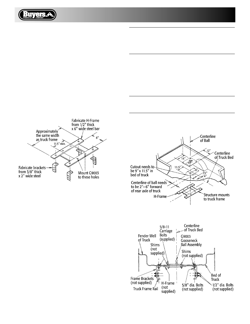
Fig. 6 Components of H-Frame
H-Frame Support Structure Method
A steel bar frame is fabricated as shown in Fig. 6.
1. Install gooseneck ball assembly in truck bed cut-out.
Insure raised ball is centered between truck bed side rails.
2. Mark and drill four 11/16" diameter holes in truck bed
using square holes in gooseneck ball assembly as a guide
for location. See Fig. 7.
3. Position H-frame assembly under floor of truck bed and
above truck frame rails. Line up with bed floor cut-out.
Wedge or clamp in place flush with bottom of truck bed.
4. Drill four 11/16" holes in H-frame using holes drilled in
step 2 as guides.
5. Install the four SAE grade 5, 5/8" diameter carriage bolts
through the gooseneck ball assembly, truck bed, and
H-frame. Install flat washers, lockwashers, and SAE grade 5
nuts. Shim, as required to level corrugations in truck bed.
6. Torque nuts to 60 ft./lbs.
WARNING:
Secure H-frame to truck frame with four 2" wide x 3/8"
thick steel angle brackets, using two per side as shown
in Fig. 6 and Fig. 8. These must be fabricated to fit a
particular truck.
7. Attach brackets to truck bed and H-frame as shown in
Fig. 8. Use SAE grade 5 hex bolts, nuts, and Iockwashers.
Torque to 110 ft/lbs.
8. Drill two 17/32" holes through bracket vertical legs and
truck frame rails.
9. Secure brackets to frame rails with SAE grade 5
1/2" dia. bolts, nuts, and lockwashers. Torque to 60 ft./lbs.
WARNING:
Do not weld brackets to the truck frame.
Use only SAE grade 5 fasteners properly torqued.
10. Proceed with installation check described on page 4.
Fig. 7 Installation of H-Frame
Fig. 8 H-Frame Cut-Away View