Bed plate support structure method – Buyers G9003 User Manual
Page 2
Quality since 1946
2
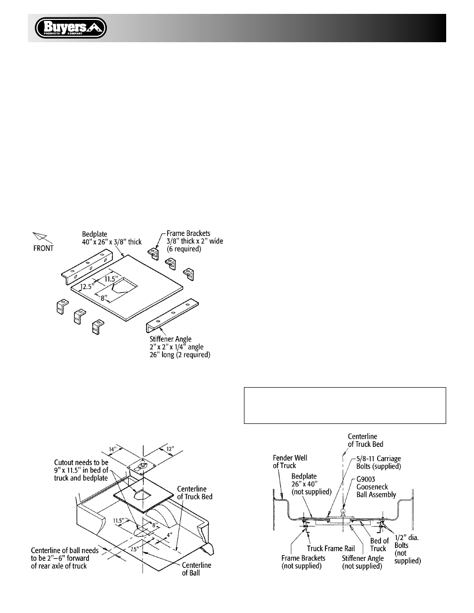
Fig. 3 Bedplate Material
Bed Plate Support Structure Method
Material to be provided by installer:
1 - 26" x 40" x 3/8" thick steel ASTM A-36 steel specifications
2 - 2" x 2" x l/4" thick steel angle iron 26" long ASTM A-36
steel specifications
6 - 3/8" thick x 2" wide steel bar (approximately 6' required:
see note*) ASTM A-36 steel specification
20 - 1/2" x (approximately 2": see note**) SAE grade 5 hex
head cap screws
20 - SAE grade 5 hex nuts
20 - 1/2" lockwashers
• Note*: As truck frames and truck beds vary, this material
must be cut and bent by the installer to fit the particular
application.
• Note**: The length of the 1/2" SAE grade 5 hex head cap
screws may vary to suit particular applications.
• Torque 1/2" SAE grade 5 fasteners to 60 ft. lbs.
• Torque 5/8" SAE grade 5 fasteners to 110 ft. lbs.
1. Place bed plate in the center of the pickup truck bed.
See Fig 4.
2. Align 8" x 11-1/2" cut-out in bed plate with corresponding
cut-out in the truck bed.
3. Place gooseneck hitch ball assembly into the hole in the
bed plate positioning as shown in figure 4.
Fig. 4 Installation of Bedplate
4. Using the four square holes in the gooseneck ball assem-
bly as guides, drill four 11/16" diameter holes through the
bed plate and the truck bed.
5. Install the four grade 5 carriage bolts through the hitch
ball assembly, bed plate and truck bed. Install the flat-
washers under the truck bed using shims to compensate
for the corrugations in the truck bed.
6. Torque the 5/8" hex nuts to 110 ft. lbs.
7. Place the two 2" x 2" x 1/4" thick stiffener angles to the
underside of the truck bed to allow the securing bolts to
pass through the truck bed and the bed plate.
8. Drill four 17/32" holes at the front end area of the bed
plate to mount the forward stiffener angle. Repeat the
operation in the rear end area of the bed plate for the rear
stiffener angle.
9. Fasten front and rear stiffener angles to the underside of
the truck bed with eight SAE grade 5 bolts, nuts and lock-
washers. Torque 1/2" grade 5 hex nuts to 60 ft./lbs.
10. Fabricate six brackets from the 3/8" x 2" bar stock. These
brackets are used to secure the bed plate to the truck frame.
Fabricate three brackets for each side of the bed plate.
11. Installed brackets must fit flush against the frame rail
and the under side of the truck bed. See Fig. 5.
12. Clamp the steel brackets along each side of the truck
frame rail. Drill 17/32" (.531) diameter holes through the
truck bed and the bed plate.
13. Use 1/2" diameter SAE grade 5 bolts, nuts and lockwash-
ers to secure the brackets to the truck bed and bed plate.
14. Drill 17/32" holes through the vertical legs of the steel
brackets and truck frame. Holes should be drilled near the
horizontal center line of the truck frame channel.
15. Use 1/2" diameter SAE grade 5 bolts, nuts and lock-
washers to secure brackets to truck frame.
16. Torque all fasteners to 60 ft./lbs.
17. Proceed with installation check on page 4.
WARNING:
Do not weld brackets to the frame of the truck.
Use SAE grade 5 fasteners properly torqued.
Fig. 5 Bedplate Cut-Away View