Buyers P45AC4 User Manual
Page 3
Quality since 1946
2
3. Clean and inspect the Body for any damage,
which may not have been detected during initial
inspection.
4. Clean the snap ring groove and verify that it has
not been crushed or broken through. If the snap
ring groove is damaged the entire hook must be
replaced.
B. Jaw Kit Installation
1. Apply a liberal amount of a good grease inside
the shaft hole in the Jaw (4). Place the Jaw into po-
sition in the Body and insert the new Shaft (5). Do
not install the Snap Ring at this time.
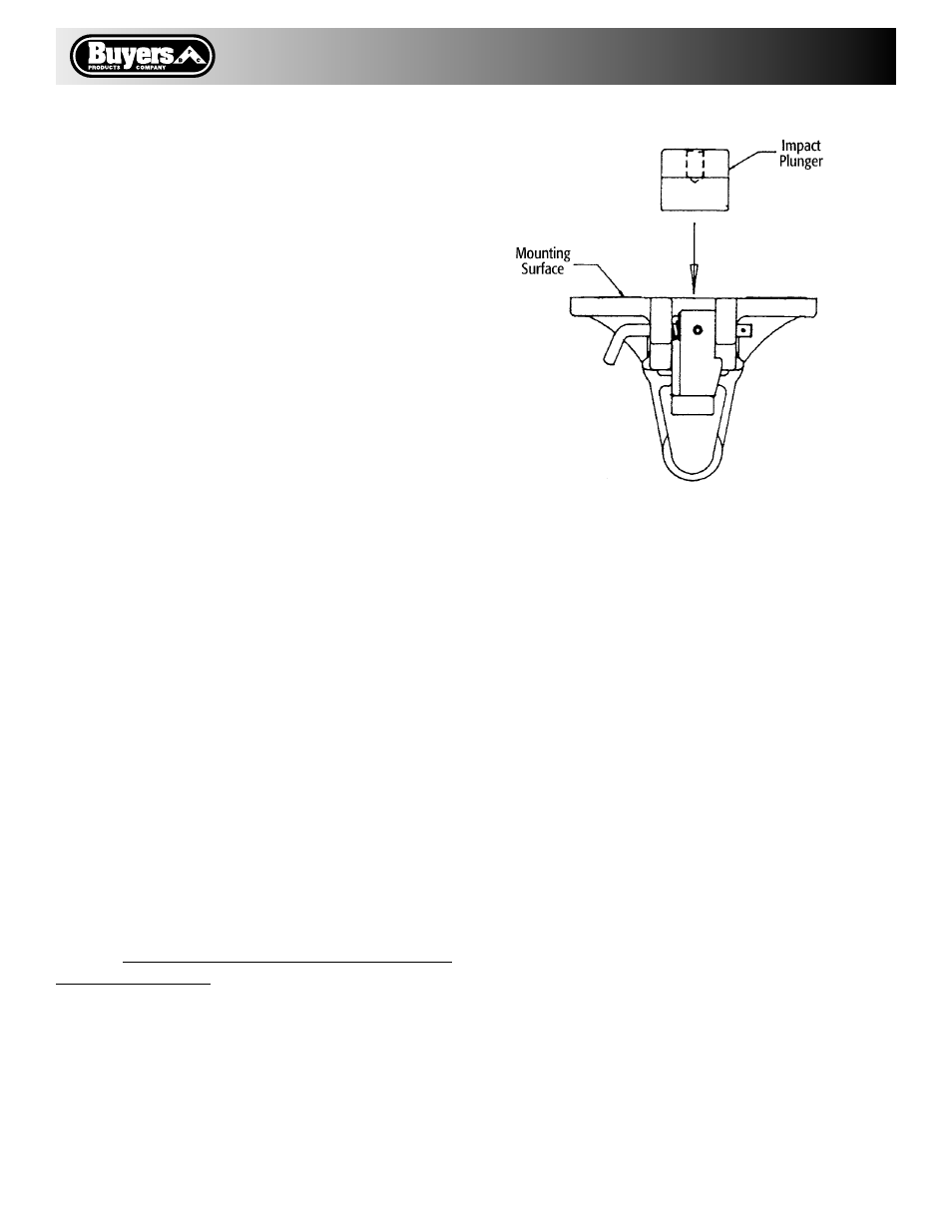
2. Place a lunette eye of the proper size onto the
hook. With the Jaw resting on the top of the horn,
verify that the Air Chamber will be able to push
the Plunger against the eye.
3. If interference of the Jaw and Plunger will not
allow the Plunger to contact the eye, remove the
Jaw and inspect for any burrs and carefully file
or grind to allow free movement. Care should be
taken not to remove an excessive amount of
material. Reinstall the Jaw and repeat step 2.
4. With the lunette eye in place and the Plunger
held against the eye, verify that the Jaw will not
lift more than 1/2” above the horn as in inspection
step C2.
C. Lock Installation
1. Reassemble the Lock mechanism as described
below in the Lock Kit C4300 section.
D. Secure the Pivot Shaft
1. Install the Rivet by providing a back stop
against the end of the Shaft on the snap ring side
of the hook and driving the Rivet (11) into the hole
provided in the end of the Shaft (eye protection re-
quired.) DO NOT USE THE SNAP RING TO BACK-
UP THE RIVETING.
2. Install the Snap Ring (10) and inspect as shown
in Fig. 1.
LOCK KIT C4300
A. Disassembly
1. Remove the Roll Pin (9) from the Actuator (7),
loosen the Set Screw (8) and pull the Actuator out
of the assembly. This will release the Lock (3) and
the Torsion Spring (6) from the assembly.
B. Lock Installation
1. Install the new Torsion Spring (6) onto the
Actuator so that the left end will rest on the shelf
provided in Body and the right end will insert into
the small hole at the back of the Lock.
2. Take note of the location of the flat area on the
Actuator shaft. Insert the Actuator through the
Lock and the right side hole in the Body. Tighten
the Set Screw (8) against the flat area on the Ac-
tuator.
3. Install the Roll Pin (9) through the hole in the
end of the Actuator.
FULL REBUILD KIT C4400
The Rebuild Kit contains all parts required to
rebuild the P45AC4 Pintle Hook Assembly. The
rebuild procedure is to follow the instructions to:
1. Replace the Jaw and Plunger per Instructions
for Kit C4200; then
2. Replace the Lock per the instructions for
Kit C4300.
3003920 Rev. A
Plunger Installation