Buyers P45AC4 User Manual
Page 2
Quality since 1946
2
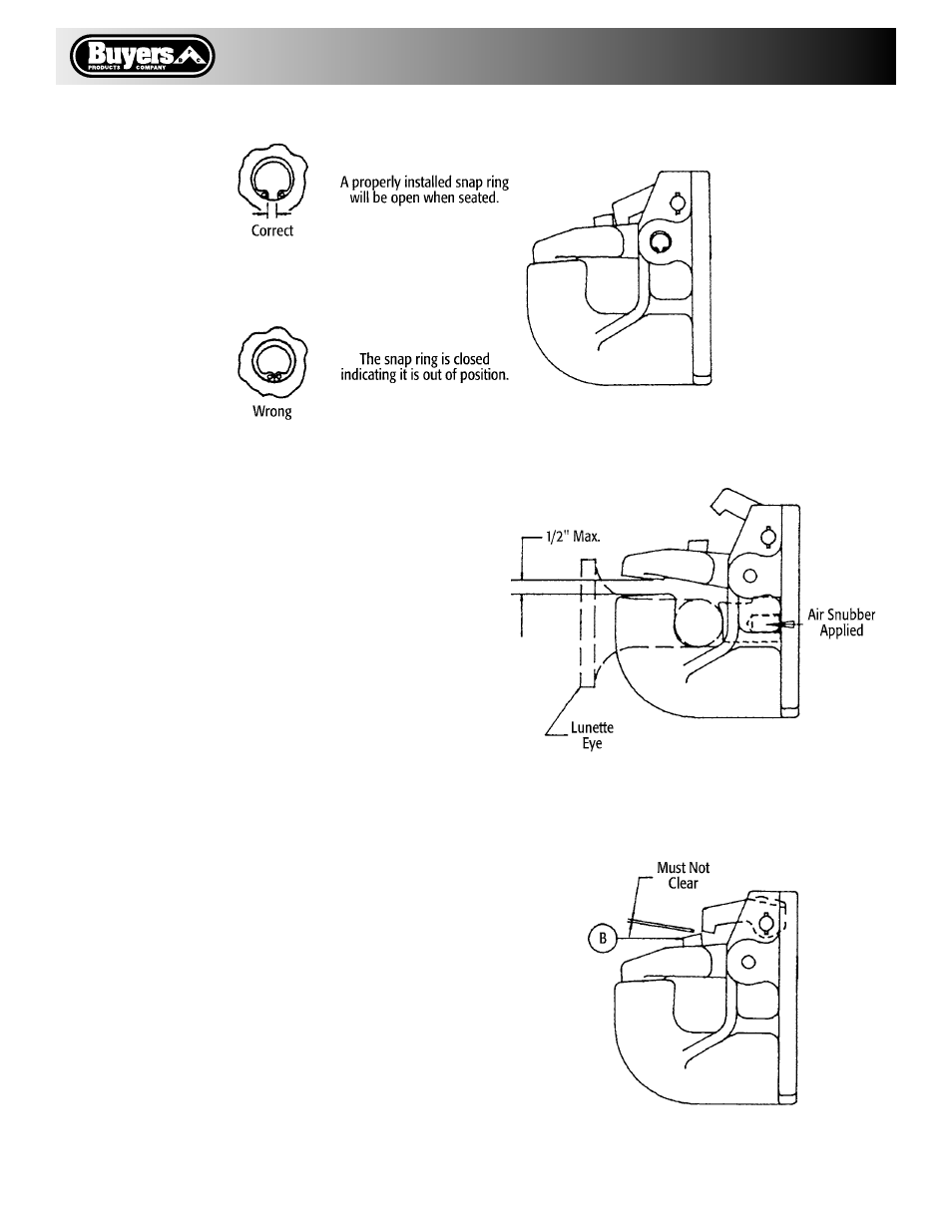
Fig. 1
Fig. 2
D. Lock Inspection
1. Grasp the Lock Actuator (7) and without com-
pressing the Spring (6) rotate the Actuator handle
to lift the Lock (3) until it stops against the Body
undercut (A). The “tooth” if the Lock must not
clear the stop (B) on top of the Jaw (4). If the lock
clears the stop (B) as shown in Fig. 3.
a. Inspect the undercut (A) on the Body, if the
undercut is not clean and square the entire hook
should be replaced.
b. If the under cut is in good condition, then install
a new Lock Kit C4300 or Rebuild Kit C4400.
E. Full Rebuild
If inspection steps A-D indicate that both the Lock
and Jaw mechanisms require replacement, then
the Rebuild Kit C4400 should be used.
JAW KIT C4200
A. Disassembly
1. Remove the Roll Pin (9) from the Actuator (7),
loosen the Set Screw (8) and pull the Actuator (7)
out of the assembly. This will release the Lock (3)
and the Torsion Spring (6) from the assembly.
2. To remove the Shaft (5) which secures the Jaw
(4), remove the head of the Rivet (11) using a cold
chisel or by grinding (eye protection is required.)
Then remove the Retaining Ring (10) with the
proper snap ring tool. Complete the disassembly
by inserting a pin through the rivet hole in the
Body and driving out the old Shaft.
Fig. 3