Vonnic C909IP H.264 Wireless 802.11b_g_n IP Network Camera User Manual
Page 7
H Series IP Camera User Manual – with Pan/Tilt of CMOS
7
2) WIFI Antenna Hole: Install the WIFI antenna.
3)
RESET Button: Press the RESET button and hold on more than 5 seconds, the
equipment will restart and recover to the factory default settings. The Pan/Tilt will move
around for one circle and finally focus to the center.
4) RJ45 Ethernet Socket: RJ45 Ethernet socket is 10/100M self-adjust. The equipment
can connect to all kinds of network equipments, such as hub, router, switch, etc.
5) Audio Input Socket: Audio input socket is designed for connecting external microphone
or line-in audio signal. Please refer to 7.1.2 and select right settings.
6) Audio Output Socket: Audio output socket is for line-out audio player, such as
headphone, speaker, etc.
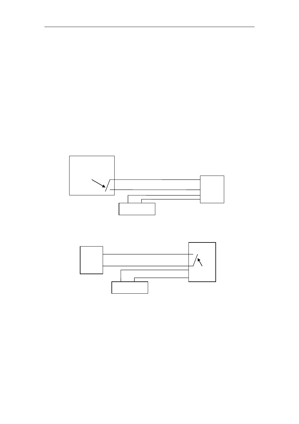
7) Alarm Output Socket: The alarm output socket is connected with a relay in the IP
camera. IP camera will control the switch to trigger the alarm bell or buzzer to alarm. The
relay is able to control the switch of a alarm whose voltage is no more than 36V, and
current is lower than 2A. Please refer to the Figure 3 for the connection of an external
alarm.
Figure 3
8) Alarming Input Pin: Please refer to the schematic Diagram of Figure 4 for how external
detector collects alarm information.
Figure 4
The detector should be switched type (always on or always off). If the detector has detected
the smoke or people or animal to enter the area, the detector will switch on or switch off. And
it will send the external alarm signal into the IP camera.
PIR
PIR Power
Input
pins
Switch
Output Pins
Alarm power
Alarm
Switch