Powersolve Power Sink Option for SM1500 User Manual
Page 2
SM1500 - P202- 206
Page 1 - 2
Datasheet - SM1500 Power Sink
2006, rev. Dec. 2009
Power Sink Spec i fi ca tions
SM15-100
option P202
SM35-45
option P203
SM52-30
option P204
SM52-AR-60
option P205
SM70-22
option P206
Sink Power Rat ing
max. peak power (elec tron i cally lim ited)
max. con tin u ous power (T
amb
. = 25 °C)
max. con tin u ous power (T
amb
. = 50 °C)
200 W
175 W
90 W
Max. du ra tion Sink Peak Power
P
sink
= 200 W, T
amb
. = 25 °C
Duty Cy cle for use at Peak Power
P
sink
= 200 W, T
amb
. = 25 °C
P
sink
<= 200 W, t
on
<= 20 s
t
on
= time, power dis si pa tion is > 0 W
t
off
= time, power dis si pa tion is 0 W
P
av
= P
peak
* t
on
/ (t
off
+ t
on
)
max. t
on
= 60 s, fol low ing t
off
= 400 s (for cool ing down)
t
on
<= 20 s / t
off
>= 10 s
av er age power <= 175 W
Max. Sink Cur rent
(V
o
>= 2 V and P <= 200 W)
Lim ited at 40 A
Lim ited at 40 A
Lim ited at 30 A
Lim ited at 40 A
Lim ited at 30 A
Pro tec tion
Elec tronic Power Limit (200 W) lim its the cur rent.
The tem per a ture of the power sink is fan con trolled and
the cir cuit shuts down in case of ther mal over load.
Re cov ery time / De vi a tion
Vo = 6 V, I
o
: +40 A → –15 A
re cov ery within 100 mV / de vi a tion:
Vo = 15 V, I
o
: +25 A → –8 A
re cov ery within 100 mV / de vi a tion:
Vo = 35 V, I
o
: +20 A → –3 A
re cov ery within 100 mV / de vi a tion:
Vo = 52 V, I
o
: +10 A → –2 A
re cov ery within 100 mV / de vi a tion:
Vo = 70 V, I
o
: +10 A → –1 A
re cov ery within 100 mV / de vi a tion:
(load cur rent switches from pos i tive
to neg a tive)
di/dt = –1.7 A/µs
300 µs / 0.20 V
di/dt = –1.6 A/µs
500 µs / 0.15 V
-
-
-
note: val ues
are typ i cal
di/dt = –1.7 A/µs
500 µs / 0.45 V
di/dt = –1.6 A/µs
600 µs / 0.40 V
di/dt = –1.3 A/µs
1.10 ms / 0.35 V
-
-
note: val ues
are typ i cal
-
di/dt = –1.6 A/µs
640 µs / 0.70 V
di/dt = –1.3 A/µs
800 µs / 0.60 V
di/dt = –0.7 A/µs
800 µs/ 0.60 V
-
note: val ues
are typ i cal
di/dt =–1.7 A/µs
700 µs / 0.50 V
di/dt = –1.3 A/µs
900 µs / 0.45 V
di/dt = –0.83 A/µs
1.30 ms / 0.35 V
di/dt = – 0.6 A/µs
1.90 ms / 0.35 V
-
note: val ues
are typ i cal
-
-
di/dt = –1.3 A/µs
800 µs / 0.70 V
di/dt = –0.6 A/µs
1.00 ms / 0.70 V
di/dt = – 0.6 A/µs
1.20 ms / 0.50 V
note: val ues
are typ i cal
Pro gram ming Down Speed
Fall time at no load (90 - 10%)
Fall time at no load with out Power Sink
Unit with Fast Pro gram ming Op tion
Fall time at no load (90 - 10%)
Fall time at no load with out Power Sink
(15 → 0 V)
8 ms
2 s
P202+P211
320 µs
60 ms
(35 → 0 V)
18 ms
5.5 s
P203+P212
570 µs
200 ms
(52 → 0 V)
10 ms
4 s
P204+P212
650 µs
270 ms
(26 / 52 → 0 V)
10 ms / 45 ms
4 s / 7.5 s
P205+P213
550 µs / 1.2 ms
170 ms / 550 ms
(70 → 0 V)
18 ms
5.5 s
P206+P214
1.0 ms
550 ms
Par al lel and Se ries op er a tion
Re fer to power sink man ual for
de tails and re stric tions.
Us ing mul ti ple units in par al lel op er a tion, only one unit can have a power sink .
Us ing mul ti ple units in se ries op er a tion, all units must have a power sink .
Notes
:
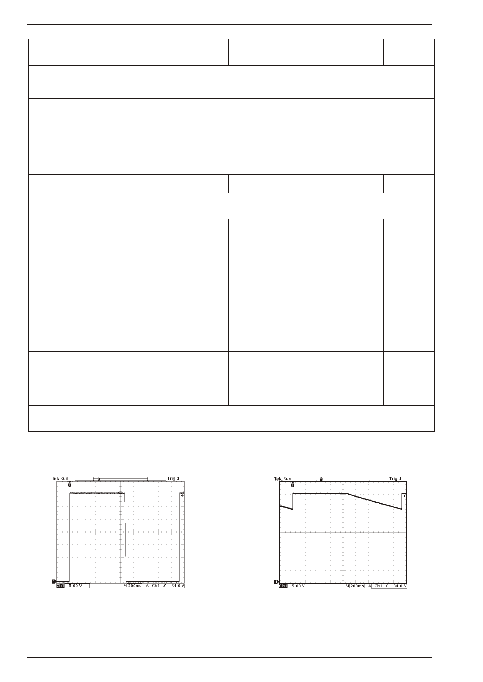
SM35-45 with Power Sink Op tion
fast dis charge of out put ca pac i tors
by the power sink circuit
trace: out put volt age
Volt age Pro gram ming Speed at NO LOAD
SM35-45 without Power Sink Op tion
slow re sponse time dur ing volt age step down,
time needed to dis charge the out put ca pac i tors
trace: out put volt age
Volt age Pro gram ming Speed at NO LOAD
• The maximum sink current at higher voltages will not be the maximum specified current due to the power limit.
For example at 30 V the maximum sink current will only be 6.7 A (30 V x 6.7 A = 200 W = maximum power).
• A higher sink current than the maximum current will cause the output voltage to rise.