Powersolve 240S Series User Manual
Page 2
Page 1 - 2
DATASHEET
Rev. Sept. 2012
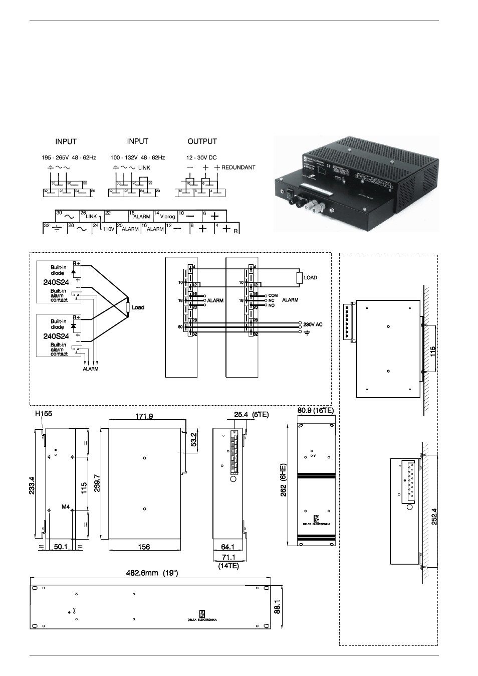
240 S 24
Two ways of ver ti cal wall
moun t ing. Mat ing con nec tor
(H15 with faston or screw
con nec tions) can be fixed
with sup plied clamp.
Mounting
:The 240S24 should be mounted vertically for optimal cooling. When mounted horizontally, put
internal current limit switch at low and keep the ambient temp. below 40 °C.
Remote sensing
:The sense points (pin 8 and 10) are internally connected to + and – output (pin 6 and pin 12), but these links can be
removed when remote sensing is required. The voltage drop across the leads plus the load can never exceed the
supply maximum output rating. For example at 24 V 8 A it is possible to compensate 6 V (3 V per lead) because the
unit can supply max. 30 V 8 A.
Remote progr.
:2 - 5 V between pin 14 and 10 gives 12 - 30 V output (internal switch in position P). Programming input is not
isolated (connected to – output).
Voltage adj. with
:Is possible if an internal link and a resistor are removed.
external potmeter
Re dun dant par al lel op er a tion with un der volt age alarm.
Out puts are sep a rated by the built-in Schottky se ries di odes.
Front panel F 16-6
Front panel F 19/2 for hor i zon tal 19" rack mount ing of one unit
240S24 with bench adapter BA 150
240S24
H 15 con nec tor