Mn b – Peerless-AV WL-SA761PU-200 - Installation User Manual
Page 15
15 of 23
ISSUED: 08-24-12 SHEET #: 180-9036-3 10-31-12
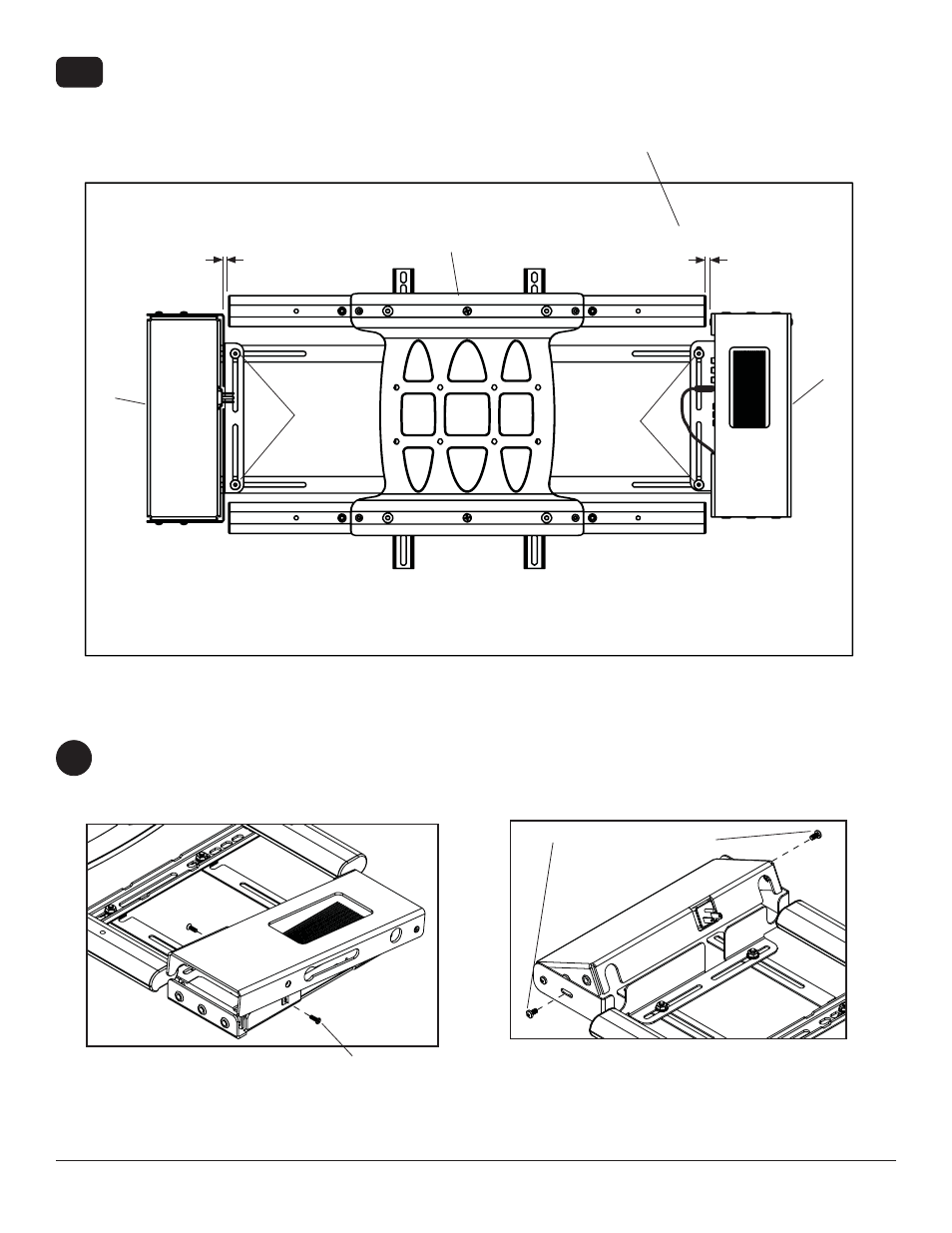
Position the wireless receiver assembly (M) and power module assembly (N) approximately 1/4" from the
universal adapter (B) as shown. Once in position, tighten the four 1/4-20 decorative screws (Q) using using 4mm
allen wrench (L) and a 7/16" open end wrench.
Skip to step 8.
7-7
1/4"
1/4"
Q
Q
DISPLAY
M
N
B
Wireless Receiver Assembly and Power Module Assembly Setup
Remove the two #8 screws securing the cover of the wireless receiver assembly as shown in detail 3. Open the
enclosure to expose the wireless receiver and IR unit. Remove the two M5 x 10mm phillips screws and open the
power enclosure as shown in detail 4.
8
DETAIL 3
DETAIL 4
#8 SCREW
M5 x 10mm SCREWS
See also other documents in the category Peerless-AV Monitors:
- SF680P - Installation (20 pages)
- SFLT646 - Sell Sheet (2 pages)
- LCT620AD - Installation (9 pages)
- HLG440-LG-Q10 - Installation (8 pages)
- LCZ-4F4G30B - Installation (26 pages)
- PRMTLU - Sell Sheet (2 pages)
- STL646 - Sell Sheet (2 pages)
- DS-VW665 - Sell Sheet (2 pages)
- HG442-HT3-S - Installation (7 pages)
- PT660 - Sell Sheet (2 pages)
- SUA765PU - Sell Sheet (2 pages)
- SF670P - Installation (20 pages)
- HF642-003 - Installation (7 pages)
- DS509 - Sell Sheet (2 pages)
- ST632-AW - Installation (29 pages)
- SFL646 - Installation (20 pages)
- PP730 - Sell Sheet (2 pages)
- HT642-003 - Sell Sheet (2 pages)
- IWB600-UNIV - Installation (18 pages)
- HS432-001 - Installation (6 pages)
- SFL637 - Sell Sheet (2 pages)
- IM746P - Installation (24 pages)
- SF630-S - Sell Sheet (2 pages)
- SA761PU - Sell Sheet (2 pages)
- DST995 - Installation (13 pages)
- MIS343 - Installation (3 pages)
- FPEPM-08 - Installation (24 pages)
- ST630-AW - Installation (26 pages)
- DS-VW765-LAND - Installation (13 pages)
- HLG452-SM-Q10 - Sell Sheet (2 pages)
- LCZ-4F4G30B - Sell Sheet (2 pages)
- SF632-AW - Sell Sheet (2 pages)
- FPZ-655 - Sell Sheet (2 pages)
- SUA746PU - Installation (29 pages)
- HS432-002 - Installation (6 pages)
- ST16D - Installation (11 pages)
- LCC-36S - Sell Sheet (2 pages)
- PRMF2X2 - Sell Sheet (2 pages)
- SF632P - Installation (24 pages)
- SC560FK - Installation (11 pages)
- MOD-FPSKIT150-B - Sell Sheet (2 pages)
- SP746PU - Sell Sheet (2 pages)
- IWB600-2SB - Installation (13 pages)
- YBT2X1 - Sell Sheet (2 pages)
- FDS-3250 - Sell Sheet (2 pages)