Peerless-AV PB-1 - Installation User Manual
Page 3
3 of 5
ISSUED: 02-26-09 SHEET #: 125-9047-1
1
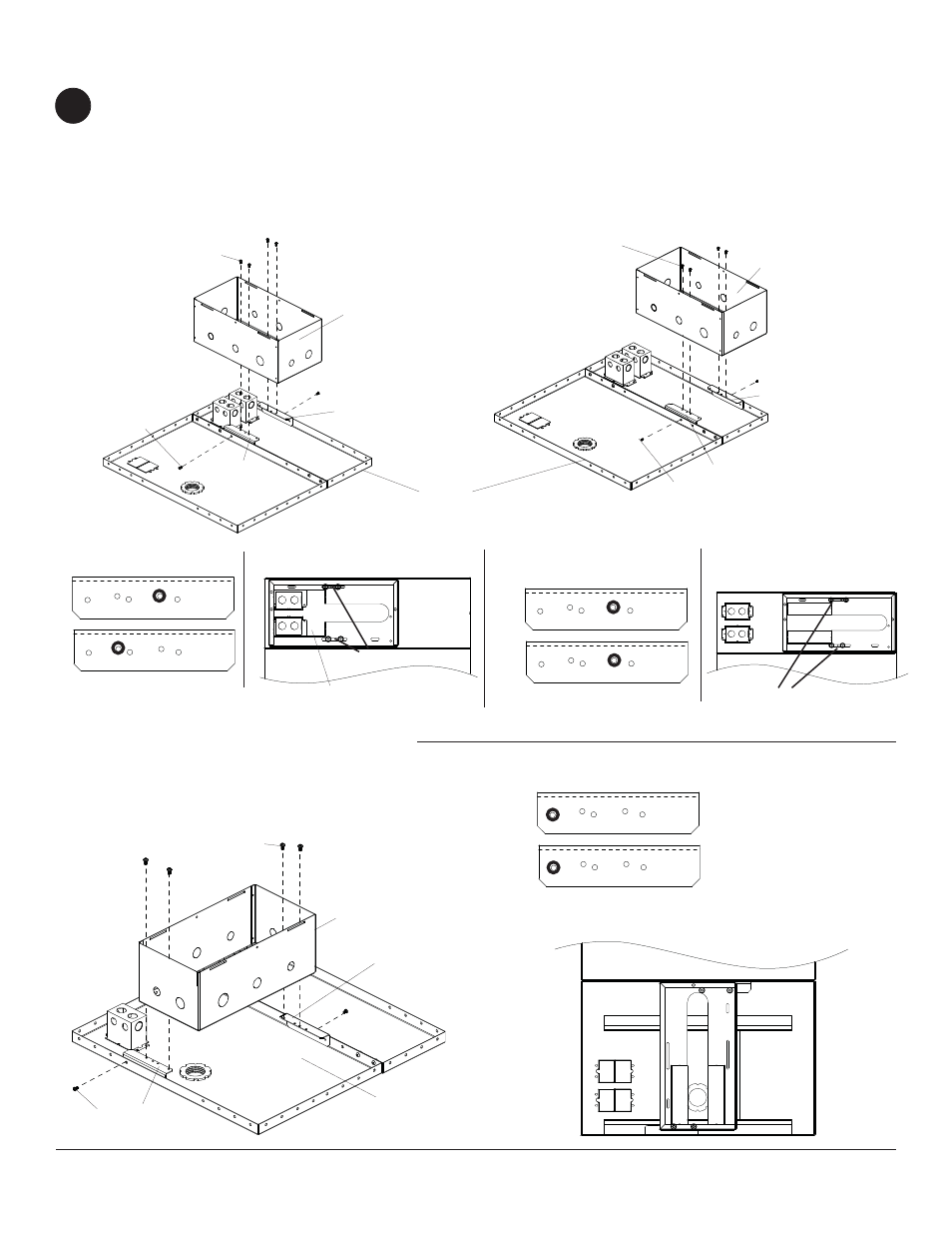
Attaching Box to CMJ455
Attaching Box to CMJ455 Option 1
Attaching Box to CMJ455 Option 2
Attaching Box to CMJ455 Option 3
B2
B1
A
D
D
B2
B1
A
D
D
B
B
A
D
D
Attach two mounting brackets (B) to CMJ500 ceiling
tray using two M5 x 10 mm phillips screws (D) in
designated holes as shown in detail 1. Attach plenum
box (A) to mounting brackets (B) using four M5 x 10
mm phillips screws (D) through designated slots
shown in detail 2.
Attach two mounting brackets (B) to CMJ500 ceiling
tray using two M5 x 10 mm phillips screws (D) in
designated holes as shown in detail 3. Attach plenum
box (A) to mounting brackets (B) using four M5 x 10
mm phillips screws (D) through designated slots
shown in detail 4.
Attach two mounting brackets (B) to CMJ500 ceiling
tray using two M5 x 10 mm phillips screws (D) in
designated holes as shown in detail 5. Attach plenum
box (A) to mounting brackets (B) using four M5 x 10
mm phillips screws (D) through designated holes
shown in detail 6.
Detail 2
Detail 1
Detail 4
Detail 3
SLOTS
SLOTS
B1
B2
B1
B2
CEILING TRAY
CEILING TRAY
Note: When using boxes remove knock out plates.
KNOCK OUT PLATES
B1
B2
Detail 6
Detail 5
VIEW ORIENTED TO
SHOW OUTSIDE FACE
OF BRACKET
VIEW ORIENTED TO SHOW
OUTSIDE FACE OF BRACKET
VIEW ORIENTED TO
SHOW OUTSIDE FACE
OF BRACKET