Peerless-AV PB-1 - Installation User Manual
Page 2
2 of 5
ISSUED: 02-26-09 SHEET #: 125-9047-1
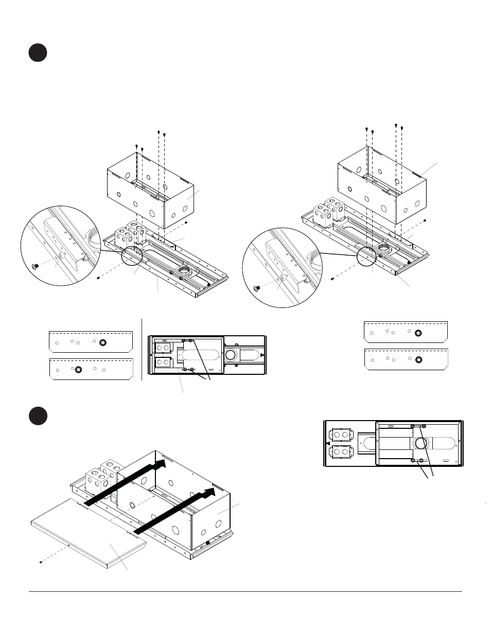
2
Attach two mounting brackets (B) to CMJ500 ceiling
tray using two M5 x 10 mm phillips screws (D). Use
spacers (E) in between CMJ500 ceiling tray and
mounting brackets (B) in designated holes as shown
in detail 1. Attach plenum box (A) to mounting
brackets (B) using four M5 x 10 mm phillips screws
(D) through designated slots shown in detail 2.
1
Attaching Box to CMJ500
Attaching Box to CMJ500 Option 1
Attaching Box to CMJ500 Option 2
Note: Before attaching top cover (D) review punch
out holes on page 1.
Slide top cover (C) into slots on box (A) and secure
using one M5 x 10 mm phillips screws (D).
A
C
B2
D
B1
B2
B1
A
E
D
D
D
A
D
Detail 2
Detail 1
Detail 4
Detail 3
SLOTS
CEILING TRAY
SLOTS
B1
B2
B1
B2
Attach two mounting brackets (B) to CMJ500 ceiling
tray using two M5 x 10 mm phillips screws (D). Use
spacers (E) in between CMJ500 ceiling tray and
mounting brackets (B) in designated holes as shown
in detail 3. Attach plenum box (A) to mounting
brackets (B) using four M5 x 10 mm phillips screws
(D) through designated slots shown in detail 4.
CEILING TRAY
Note: When using boxes remove knock out plates.
KNOCK OUT PLATES
VIEW ORIENTED TO SHOW OUTSIDE
FACE OF BRACKET
VIEW ORIENTED TO SHOW OUTSIDE
FACE OF BRACKET
E
E