B&B Electronics 850-10960-ACDC - Manual User Manual
Page 9
4
5. Reduced Air Flow - Installation of the equipment in a rack should be such that
the amount of air flow required for safe operation of the equipment is not
compromised.
6. Mechanical Loading - Mounting of the equipment in the rack should be such
that a hazardous condition is not achieved due to uneven mechanical loading.
7. Circuit Overloading - Consideration should be given to the connection of the
equipment to the supply circuit and the effect that overloading of the circuits
might have on over current protection and supply wiring.
8. Reliable Grounding - Reliable grounding of Rackmounted equipment should be
maintained. Particular attention should be given to supply connections other
than direct connections to the branch circuit (e.g., use of power strips).
9. All AC and DC versions are intended for use in a Restricted Access Location
(RAL).
Wiring Instruction Guidelines for DC Module in 2DC and ACDC
1. Connection of a suitable grounding conductor to the grounding terminal
at each power supply module (a minimum 14AWG copper conductor
should be suitable based on a 15A circuit breaker requirement).
2. Connection of suitable supply wiring to the plus and minus terminals at
each power supply module (a minimum 14AWG copper conductors is
considered suitable based on the 11A input maximum). The input
terminal block at the power supply module is suitable for 22-14 AWG
copper wire.
3. A suitable listed circuit breaker shall be provided in the building
installation as the unit's disconnect device. The branch circuit rating (i.e.
minimum 15A listed circuit breaker, etc.).
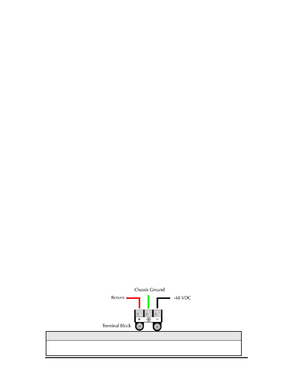
DC Power Supply Module Wiring Instructions
The following diagram shows the wiring configuration for a -48 VDC power supply
module for the iMediaChassis/20-2DC and iMediaChassis/20-ACDC.
NOTE
The chassis is protected against incorrect wiring configurations. When wired incorrectly, the
chassis will not function, but no damage will occur.