B&B Electronics 850-10960-ACDC - Manual User Manual
Page 24
19
5. If mounting the chassis on a wall, place two #10 panhead screws (not supplied)
on the wall according to the distance of the holes on the chassis, and then hang
the unit on the screws.
6. All versions are intended for use in a Restricted Access Location (RAL).
7. A readily accessible disconnect device shall be incorporated in the building
installation wiring.
8. A suitable listed circuit breaker shall be provided in the building installation as
the unit’s disconnect device. The branch circuit rating (i.e. minimum 15A listed
circuit breaker, etc.).
DC Power Wiring, Replacing Power Supply Modules and Fans
DC Power Supply Module Wiring Instructions
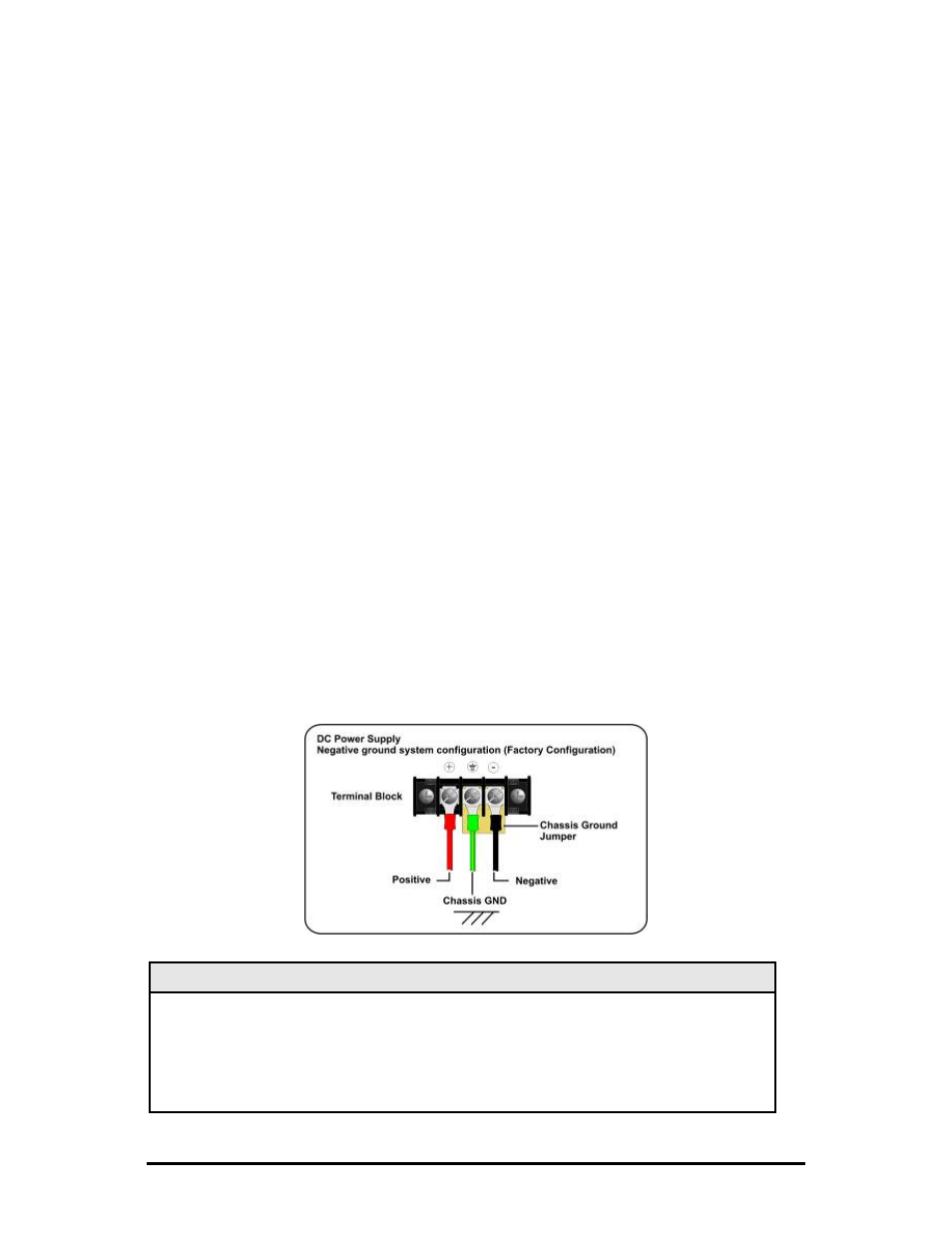
The following image shows the wiring configuration for a 48 VDC power supply in a
negative ground system application. For positive ground system applications remove
the chassis ground shorting jumper and connect it between the positive terminal and
the chassis ground terminal. Alternatively, the chassis grounding jumper can be
eliminated and the chassis ground connected at the power source. The ground
terminal and the negative terminal are not connected inside the iMediaChassis/3.
DC Power Supply
Negative ground system configuration (default position)
NOTE
Incorrect wiring will result in chassis malfunction.
The iMediaChassis/3 is compliant with Isolated Grounding Plane practices. The POSITIVE
and NEGATIVE terminals are isolated from chassis ground and must have a ground
reference at the power-sourcing equipment.