B&B Electronics 850-10960-ACDC - Manual User Manual
Page 7
2
Alarm Reset Button
When one power supply module malfunctions, an audible alarm sounds indicating
the loss of the power module. The alarm can be silenced by pressing the Alarm Reset
Button, located next to the power connector on the power supply module. If this
occurs, remove and replace the power supply module immediately. (LEDs on the
Management Module and the power supply module itself also indicate power supply
module failures.)
Last Gasp Alarm
The iMediaChassis series includes the Last Gasp trap feature, “Remote Chassis
Down”, which sends a Trap when the following occurs:
• Both power supply modules malfunction
• Both power supply modules are powered down
• When the AC line fails
Temperature Gauge
The iMediaChassis/20 includes a temperature monitoring gauge with a heat sensor on
the backplane of the chassis. Users define a threshold for chassis temperature via
SNMP. If the chassis’ temperature rises above the specified level, the SNMP agent
sends a trap (configured in iView²) to the administrator. There is also an LED
indicator on the SNMP Management Module for chassis temperature.
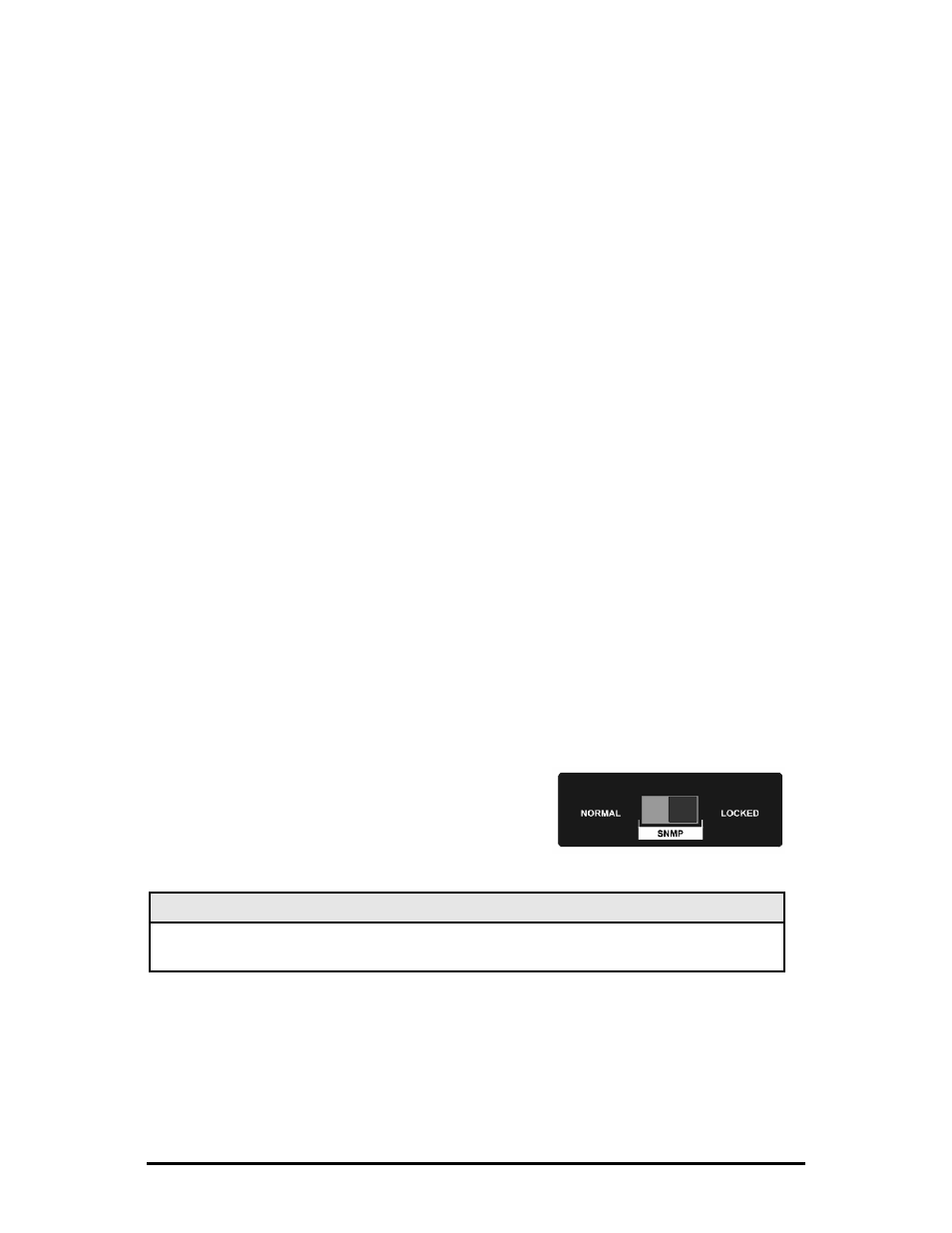
SNMP Write Lock
There is an SNMP Write Lock switch located below slot #3 on the front of the
iMediaChassis/20. The SNMP Write Lock switch prevents a new management board
from re-configuring the application module settings
(e.g., the status of features such as LinkLoss,
FiberAlert, Force mode, etc.) made via SNMP on
any previous Management Modules.
NOTE
Leave this switch in the NORMAL position during day-to-day operation; the LOCKED
position should only be used when changing the SNMP management board.
The SNMP Management Module can be removed and replaced as necessary. Refer
to the SNMP Management Module manual for complete instructions about
configuration and operation. If an SNMP Management Module is installed, refer to
the LED panel below for indicators of Link, Temperature, Power supply modules and
other functions.