3 rf connectors configuration – Rainbow Electronics MG260 User Manual
Page 24
MG260 Product Specification
This document is the sole and exclusive property of FLYFOT. Not to be distributed or divulged without prior written
agreement.
GSM
ANTENNA
PORT
GPS
ANTENNA
PORT
Modes
Functions
Internal mode
GPS is controlled by the customer application using specific AT commands
through the GSM serial link.
GPS information can be retrieved either by specific AT commands on GSM
serial link or directly on the GPS serial link (NMEA frames).
The GSM serial link is used for AT commands to control both GSM/GPRS
and GPS.
The choice between these modes is available by software. See Specific AT commands for
GPS management document [5] for details.
The MG260 module is a DCE (Data Communication Equipment).
The names of the MG260 module serial link signals are given view from the application
DTE (Data Terminal Equipment).
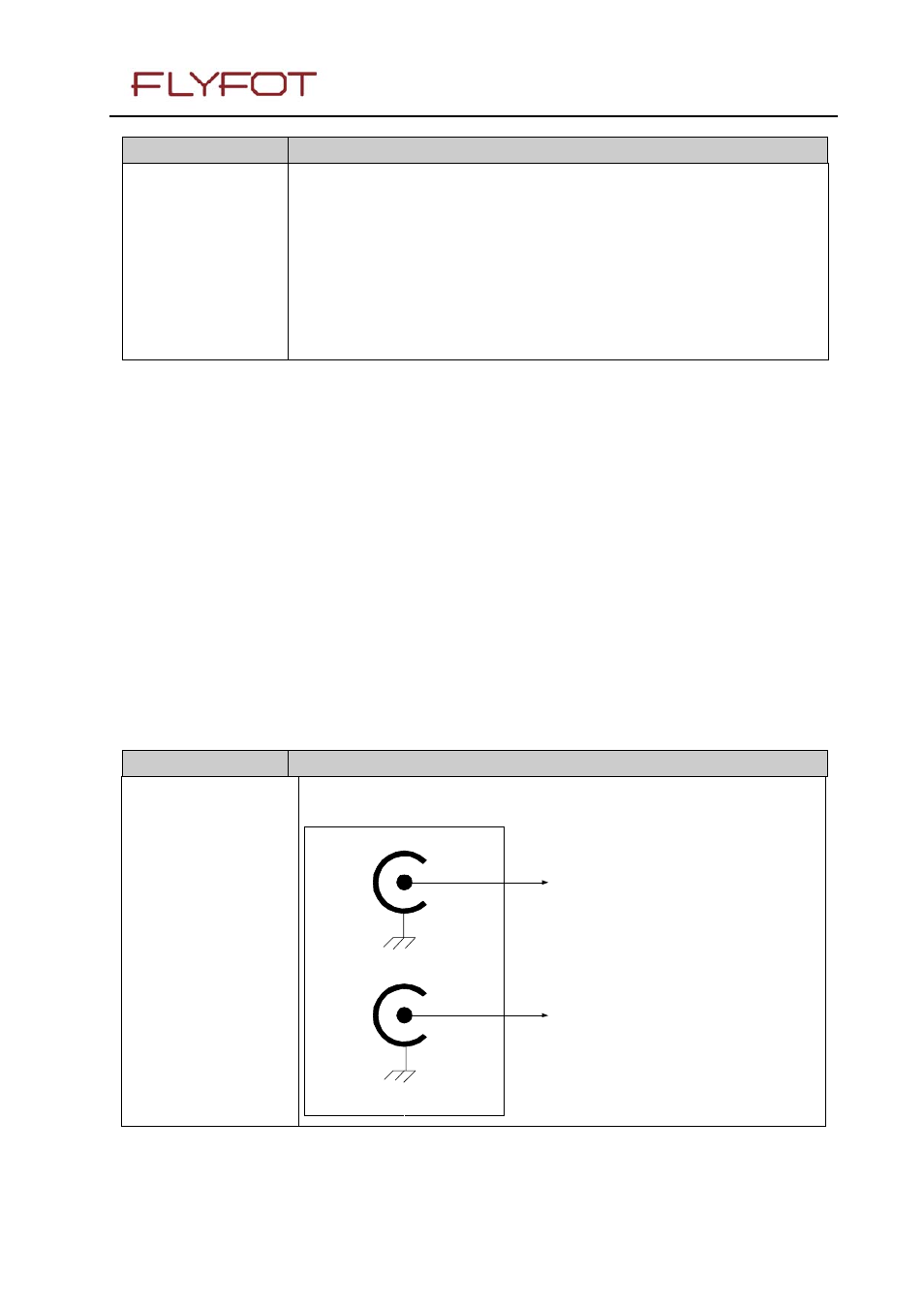
1.7.3 RF connectors configuration
Modes
Functions
Configuration
Dedicated GSM and GPS antennas are connected by TWO separate RF
connectors.
CONNECTED TO
GSM ANTENNA
CONNECTED TO
GPS ANTENNA