2 operation mode summary – Rainbow Electronics AT45DB321D User Manual
Page 27
27
3597J–DFLASH–4/08
AT45DB321D
Note:
Based on JEDEC publication 106 (JEP106), Manufacturer ID data can be comprised of any number of bytes. Some manufacturers may have
Manufacturer ID codes that are two, three or even four bytes long with the first byte(s) in the sequence being 7FH. A system should detect code
7FH as a “Continuation Code” and continue to read Manufacturer ID bytes. The first non-7FH byte would signify the last byte of Manufacturer ID
data. For Atmel (and some other manufacturers), the Manufacturer ID data is comprised of only one byte.
14.2
Operation Mode Summary
The commands described previously can be grouped into four different categories to better
describe which commands can be executed at what times.
Group A commands consist of:
1.
Main Memory Page Read
2.
Continuous Array Read
3.
Read Sector Protection Register
4.
Read Sector Lockdown Register
5.
Read Security Register
Group B commands consist of:
1.
Page Erase
2.
Block Erase
3.
Sector Erase
4.
Chip Erase
5.
Main Memory Page to Buffer 1 (or 2) Transfer
6.
Main Memory Page to Buffer 1 (or 2) Compare
7.
Buffer 1 (or 2) to Main Memory Page Program with Built-in Erase
8.
Buffer 1 (or 2) to Main Memory Page Program without Built-in Erase
9.
Main Memory Page Program through Buffer 1 (or 2)
10. Auto Page Rewrite
Group C commands consist of:
1.
Buffer 1 (or 2) Read
2.
Buffer 1 (or 2) Write
3.
Status Register Read
4.
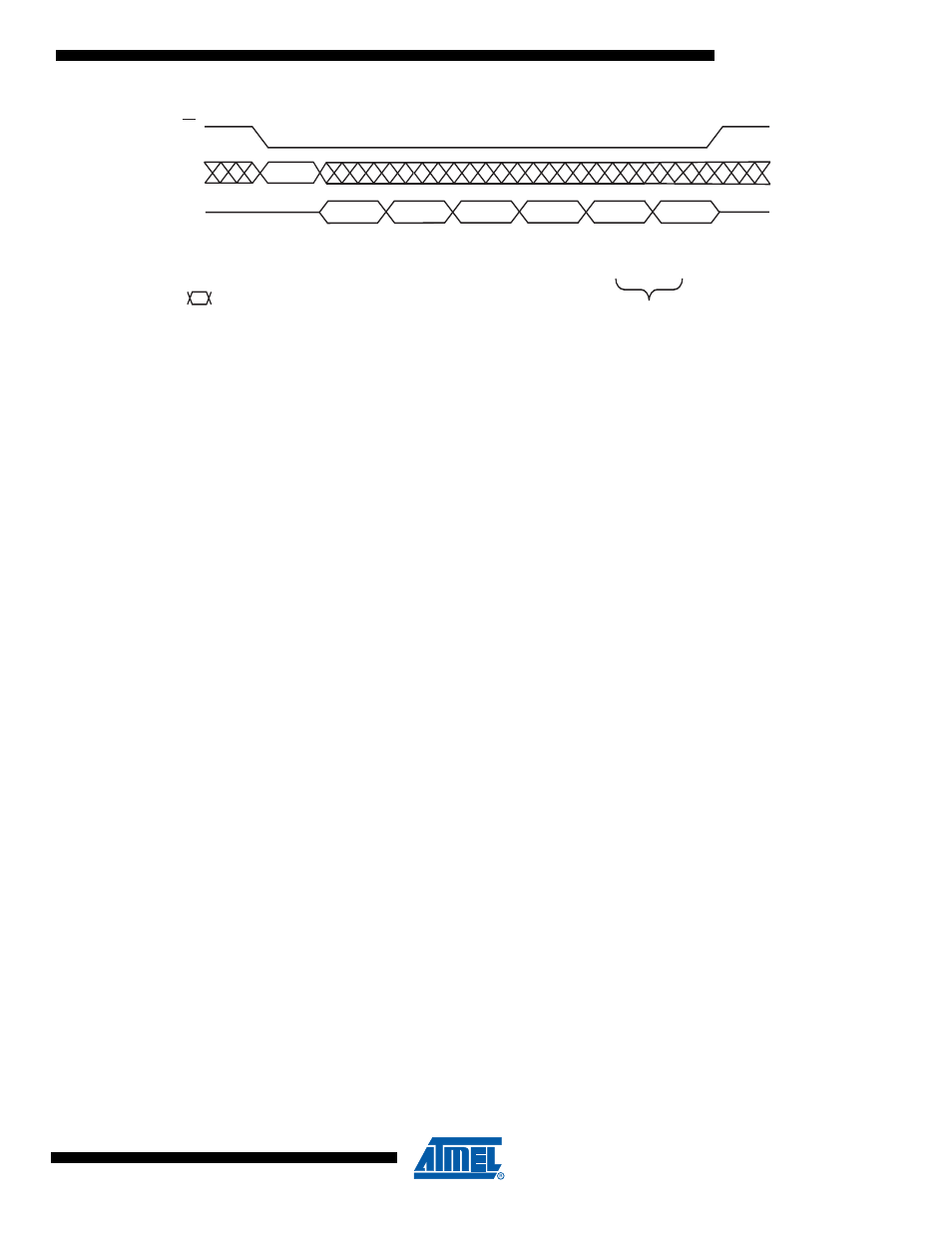
Manufacturer and Device ID Read
9FH
Manufacturer ID
Byte 1
Device ID
Byte 2
Device ID
Byte 3
This information would only be output
if the Extended Device Information String Length
value was something other than 00H.
Extended
Device
Information
String Length
Extended
Device
Information
Byte x
Extended
Device
Information
Byte x + 1
CS
1FH
27H
00H
01H
Data
Data
SI
SO
Opcode
Each transition
represents 8 bits