Ac characteristics for read operation, Ac waveforms for read operation(1), Ac waveforms for read operatio n – Rainbow Electronics AT27LV520 User Manual
Page 5
AT27LV520
5
Note:
3, 4, 5 — see AC Waveforms for Read Operation
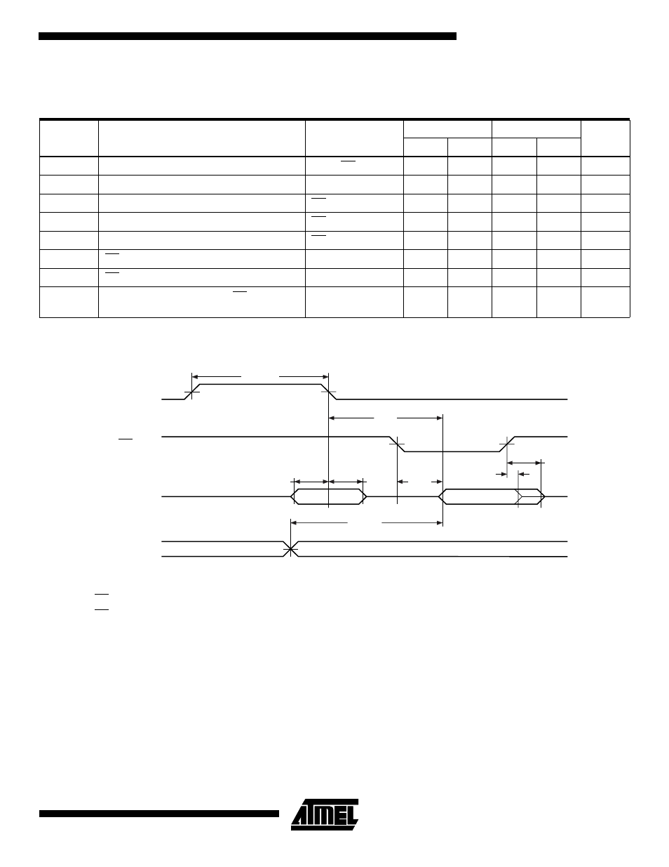
AC Waveforms for Read Operation
Notes:
1. Timing measurement reference levels for all speed grades are V
OL
= 0.8V and V
OH
= 2.0V. Input AC drive levels are V
IL
=
0.45V and V
IH
= 2.4V.
2. OE/V
PP
may be delayed up to t
CE
- t
OE
after the address is valid without impact on t
CE
.
3. OE/V
PP
may be delayed up to t
ACC
- t
OE
after the address is valid without impact on t
ACC
.
4. This parameter is only sampled and is not 100% tested.
5. Output float is defined as the point when data is no longer driven.
AC Characteristics for Read Operation
V
CC
= 3.0V to 3.6V and 4.5V to 5.5V
Symbol
Parameter
Condition
AT27LV520-70
AT27LV520-90
Units
Min
Max
Min
Max
t
ACC
Address to Output Delay
ALE = OE/V
PP
= V
IL
70
90
ns
t
CE
Address Latch Enable Low to Output Delay
Address Valid
55
70
ns
t
AS
Address Setup Time
OE/V
PP
= V
IH
12
15
ns
t
AH
Address Hold Time
OE/V
PP
= V
IH
12
15
ns
t
ALE
Address Latch Enable Width
OE/V
PP
= V
IH
40
45
ns
t
OE
OE/V
PP
to Output Delay
ALE = V
IL
30
35
ns
t
DF
OE/V
PP
High to Output Float
ALE = V
IL
25
25
ns
t
OH
Output Hold from Address or OE/V
PP
,
whichever occurred first
ALE = V
IL
7
0
ns
ALE
OE/V
PP
AD7 - AD0
A15 - A8
tALE
ADDRESS IN
tAS
tAH
DATA OUT
tOE
tACC
tDF
tOH
tCE