Cs si so – Rainbow Electronics AT26DF081A User Manual
Page 12
12
3600H–DFLASH–11/2012
AT26DF081A
sectors; therefore, once the highest unprotected memory location in a programming sequence
has been programmed, the device will automatically exit the Sequential Program mode and
reset the WEL bit in the Status Register. For example, if Sector 1 was protected and Sector 0
was currently being programmed, once the last byte of Sector 0 was programmed, the Sequen-
tial Program mode would automatically end. To continue programming with Sector 2, the
Sequential Program mode would have to be restarted by supplying the ADh or AFh opcode, the
three address bytes, and the first byte of Sector 2 to program.
While the device is programming a byte, the Status Register can be read and will indicate that
the device is busy. For faster throughput, it is recommended that the Status Register be polled at
the end of each program cycle rather than waiting the t
BP
time to determine if the byte has fin-
ished programming before starting the next Sequential Program mode cycle.
The device also incorporates an intelligent programming algorithm that can detect when a byte
location fails to program properly. If a programming error arises, it will be indicated by the EPE
bit in the Status Register.
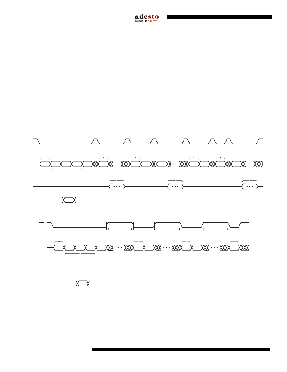
Figure 8-3.
Sequential Program Mode – Status Register Polling
Figure 8-4.
Sequential Program Mode – Waiting Maximum Byte Program Time
CS
SI
SO
Opcode A
23-16
A
15-8
A
7-0
05h
Data
HIGH-IMPEDANCE
Opcode
Data
05h
04h
Opcode
Data
05h
STATUS REGISTER
DATA
STATUS REGISTER
DATA
STATUS REGISTER
DATA
Seqeuntial Program Mode
Command
First Address to Program
Status Register Read
Command
Write Disable
Command
Seqeuntial Program Mode
Command
Seqeuntial Program Mode
Command
Note: Each transition
shown for SI represents one byte (8 bits)
CS
SI
SO
Opcode A
23-16
A
15-8
A
7-0
Data
HIGH-IMPEDANCE
Opcode
Data
04h
Opcode
Data
Seqeuntial Program Mode
Command
First Address to Program
Write Disable
Command
Seqeuntial Program Mode
Command
Seqeuntial Program Mode
Command
Note: Each transition
shown for SI represents one byte (8 bits)
t
BP
t
BP
t
BP