20s2 – soic, End view, Side view top view – Rainbow Electronics AT17LV040 User Manual
Page 21
21
AT17LV65/128/256/512/010/002/040
2321D–CNFG–10/02
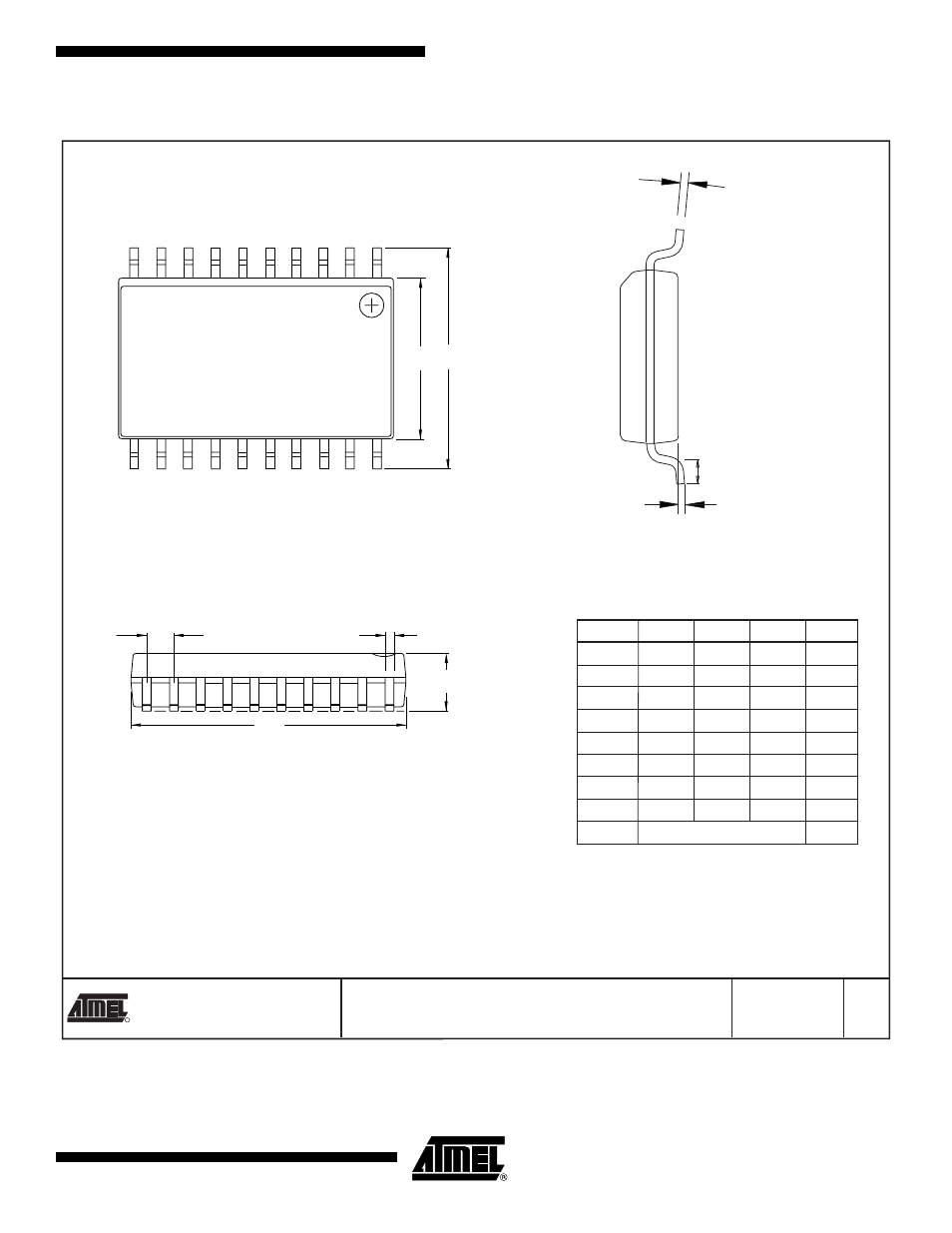
20S2 – SOIC
2325 Orchard Parkway
San Jose, CA 95131
TITLE
DRAWING NO.
R
REV.
20S2, 20-lead, 0.300" Wide Body, Plastic Gull
Wing Small Outline Package (SOIC)
1/9/02
20S2
A
L
A1
End View
Side View
Top View
H
E
b
N
1
e
A
D
C
COMMON DIMENSIONS
(Unit of Measure = inches)
SYMBOL
MIN
NOM
MAX
NOTE
Notes: 1. This drawing is for general information only; refer to JEDEC Drawing MS-013, Variation AC for additional information.
2. Dimension "D" does not include mold Flash, protrusions or gate burrs. Mold Flash, protrusions and gate burrs shall not exceed
0.15 mm (0.006") per side.
3. Dimension "E" does not include inter-lead Flash or protrusion. Inter-lead Flash and protrusions shall not exceed 0.25 mm
(0.010") per side.
4. "L" is the length of the terminal for soldering to a substrate.
5. The lead width "b", as measured 0.36 mm (0.014") or greater above the seating plane, shall not exceed a maximum value of 0.61 mm
(0.024") per side.
A
0.0926
0.1043
A1
0.0040
0.0118
b
0.0130
0.0200
4
C
0.0091
0.0125
D
0.4961
0.5118
1
E
0.2914
0.2992
2
H
0.3940
0.4190
L
0.0160
0.050
3
e
0.050 BSC