Adc data register – adcl and adch – Rainbow Electronics AT90LS4433 User Manual
Page 69
69
AT90S/LS4433
1042G–AVR–09/02
• Bit 5 – ADFR: ADC Free Run Select
When this bit is set (one), the ADC operates in Free Run mode. In this mode, the ADC
samples and updates the Data Registers continuously. Clearing this bit (zero) will termi-
nate Free Run mode.
• Bit 4 – ADIF: ADC Interrupt Flag
This bit is set (one) when an ADC conversion completes and the Data Registers are
updated. The ADC Conversion Complete interrupt is executed if the ADIE bit and the I-
bit in SREG are set (one). ADIF is cleared by hardware when executing the correspond-
ing interrupt handling vector. Alternatively, ADIF is cleared by writing a logical “1” to the
flag. Beware that if doing a Read-Modify-Write on ADCSR, a pending interrupt can be
disabled. This also applies if the SBI and CBI instructions are used.
• Bit 3 – ADIE: ADC Interrupt Enable
When this bit is set (one) and the I-bit in SREG is set (one), the ADC Conversion Com-
plete interrupt is activated.
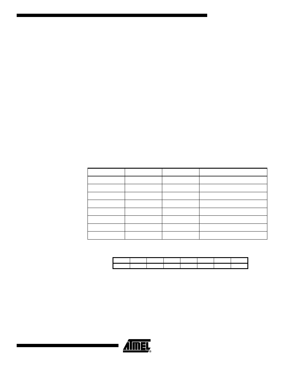
• Bits 2..0 – ADPS2..ADPS0: ADC Prescaler Select Bits
These bits determine the division factor between the XTAL frequency and the input
clock to the ADC.
ADC Data Register – ADCL
AND ADCH
When an ADC conversion is complete, the result is found in these two registers. In Free
Run mode, it is essential that both registers are read and that ADCL is read before
ADCH.
Table 22. ADC Prescaler Selections
ADPS2
ADPS1
ADPS0
Division Factor
0
0
0
2
0
0
1
2
0
1
0
4
0
1
1
8
1
0
0
16
1
0
1
32
1
1
0
64
1
1
1
128
Bit
15
14
13
12
11
10
9
8
$05 ($25)
–
–
–
–
–
–
ADC9
ADC8
ADCH
$04 ($26)
ADC7
ADC6
ADC5
ADC4
ADC3
ADC2
ADC1
ADC0
ADCL
7
6
5
4
3
2
1
0
Read/Write
R
R
R
R
R
R
R
R
R
R
R
R
R
R
R
R
Initial Value
0
0
0
0
0
0
0
0
0
0
0
0
0
0
0
0