Rainbow Electronics AT90LS4433 User Manual
Page 63
63
AT90S/LS4433
1042G–AVR–09/02
• Bit 4 – ACI: Analog Comparator Interrupt Flag
This bit is set (one) when a comparator output event triggers the interrupt mode defined
by ACI1 and ACI0. The Analog Comparator Interrupt routine is executed if the ACIE bit
is set (one) and the I-bit in SREG is set (one). ACI is cleared by hardware when execut-
ing the corresponding interrupt handling vector. Alternatively, ACI is cleared by writing a
logical “1” to the flag.
• Bit 3 – ACIE: Analog Comparator Interrupt Enable
When the ACIE bit is set (one) and the I-bit in the Status Register is set (one), the Ana-
log Comparator interrupt is activated. When cleared (zero), the interrupt is disabled.
• Bit 2 – ACIC: Analog Comparator Input Capture Enable
When set (one), this bit enables the Input Capture function in Timer/Counter1 to be trig-
gered by the Analog Comparator. The comparator output is, in this case, directly
connected to the Input Capture front-end logic, making the comparator utilize the noise
canceler and edge select features of the Timer/Counter1 Input Capture interrupt. When
cleared (zero), no connection between the Analog Comparator and the Input Capture
function is given. To make the comparator trigger the Timer/Counter1 Input Capture
interrupt, the TICIE1 bit in the Timer Interrupt Mask Register (TIMSK) must be set (one).
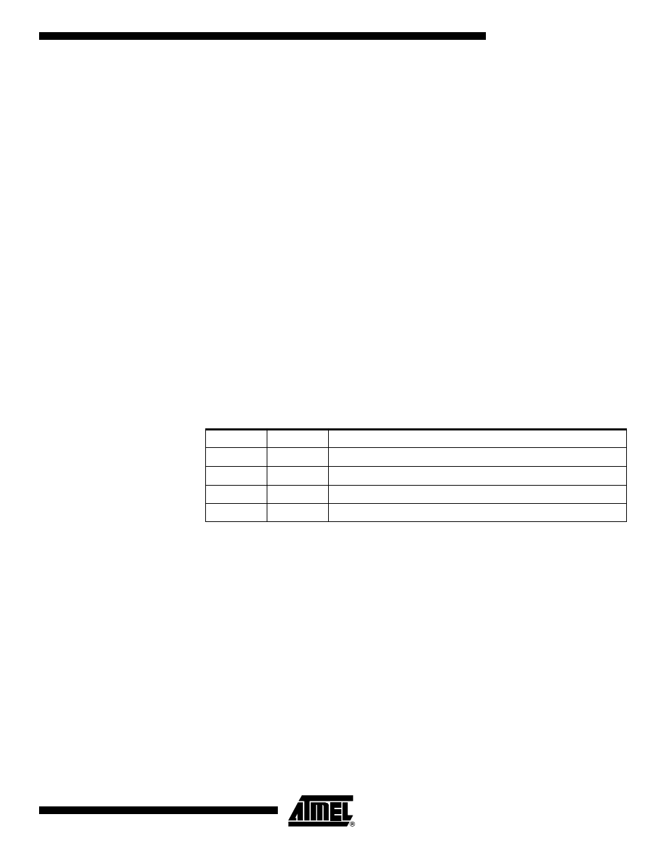
• Bits 1, 0 – ACIS1, ACIS0: Analog Comparator Interrupt Mode Select
These bits determine which comparator events trigger the Analog Comparator interrupt.
The different settings are shown in Table 20.
Note:
1. When changing the ACIS1/ACIS0 bits, the Analog Comparator interrupt must be dis-
abled by clearing its Interrupt Enable bit in the ACSR Register. Otherwise, an
interrupt can occur when the bits are changed.
Caution: Using the SBI or CBI instruction on bits other than ACI in this register will write
a one back into ACI if it is read as set, thus clearing the flag.
Table 20. ACIS1/ACIS0 Settings
ACIS1
ACIS0
Interrupt Mode
0
0
Comparator Interrupt on Output Toggle.
0
1
Reserved
1
0
Comparator Interrupt on Falling Output Edge.
1
1
Comparator Interrupt on Rising Output Edge.