Spi control register – spcr – Rainbow Electronics AT90LS4433 User Manual
Page 51
51
AT90S/LS4433
1042G–AVR–09/02
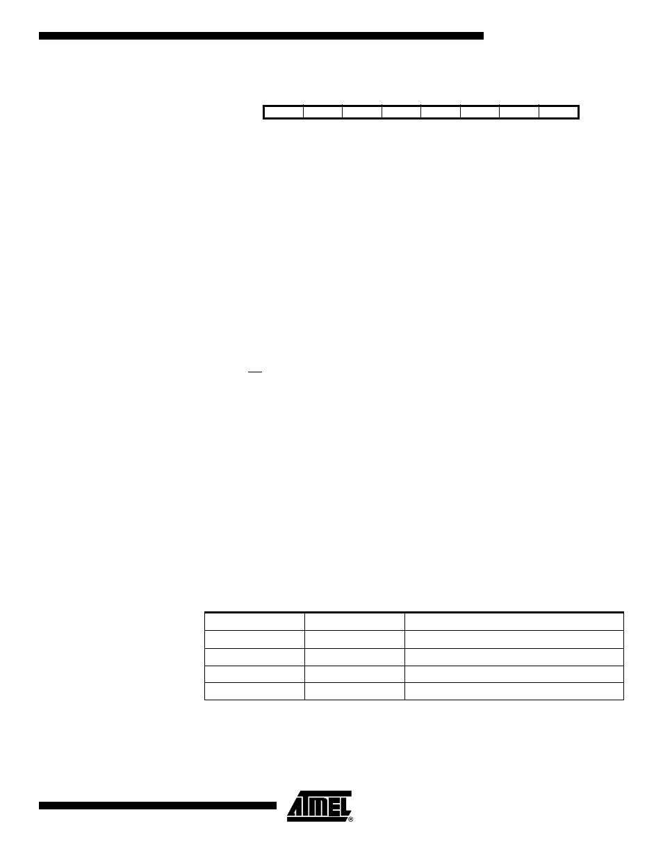
SPI Control Register – SPCR
• Bit 7 – SPIE: SPI Interrupt Enable
This bit causes the SPI interrupt to be executed if SPIF bit in the SPSR Register is set
and the global interrupts are enabled.
• Bit 6 – SPE: SPI Enable
When the SPE bit is set (one), the SPI is enabled. This bit must be set to enable any SPI
operations.
• Bit 5 – DORD: Data Order
When the DORD bit is set (one), the LSB of the data word is transmitted first.
When the DORD bit is cleared (zero), the MSB of the data word is transmitted first.
• Bit 4 – MSTR: Master/Slave Select
This bit selects Master SPI mode when set (one), and Slave SPI mode when cleared
(zero). If SS is configured as an input and is driven low while MSTR is set, MSTR will be
cleared and SPIF in SPSR will become set. The user will then have to set MSTR to re-
enable SPI Master mode.
• Bit 3 – CPOL: Clock Polarity
When this bit is set (one), SCK is high when idle. When CPOL is cleared (zero), SCK is
low when idle. Refer to Figure 38 and Figure 39 for additional information.
• Bit 2 – CPHA: Clock Phase
Refer to Figure 38 or Figure 39 for the functionality of this bit.
• Bits 1, 0 – SPR1, SPR0: SPI Clock Rate Select 1 and 0
These two bits control the SCK rate of the device configured as a Master. SPR1 and
SPR0 have no effect on the Slave. The relationship between SCK and the Oscillator
clock frequency (f
cl
) is shown in Table 18.
Bit
7
6
5
4
3
2
1
0
$0D ($2D)
SPIE
SPE
DORD
MSTR
CPOL
CPHA
SPR1
SPR0
SPCR
Read/Write
R/W
R/W
R/W
R/W
R/W
R/W
R/W
R/W
Initial Value
0
0
0
0
0
0
0
0
Table 18. Relationship between SCK and the Oscillator Frequency
SPR1
SPR0
SCK Frequency
0
0
f
cl
/4
0
1
f
cl
/16
1
0
f
cl
/64
1
1
f
cl
/128