Timer counter0 – tcnt0, Bit timer/counter1 – Rainbow Electronics AT90LS4433 User Manual
Page 35
35
AT90S/LS4433
1042G–AVR–09/02
The Stop condition provides a Timer Enable/Disable function. The prescaled CK modes
are scaled directly from the CK Oscillator clock. If the external pin modes are used for
Timer/Counter0, transitions on PD4/(T0) will clock the counter even if the pin is config-
ured as an output. This feature can give the user software control of the counting.
Timer Counter0 – TCNT0
The Timer/Counter0 is realized as an up-counter with read and write access. If the
Timer/Counter0 is written and a clock source is present, the Timer/Counter0 continues
counting in the clock cycle following the write operation.
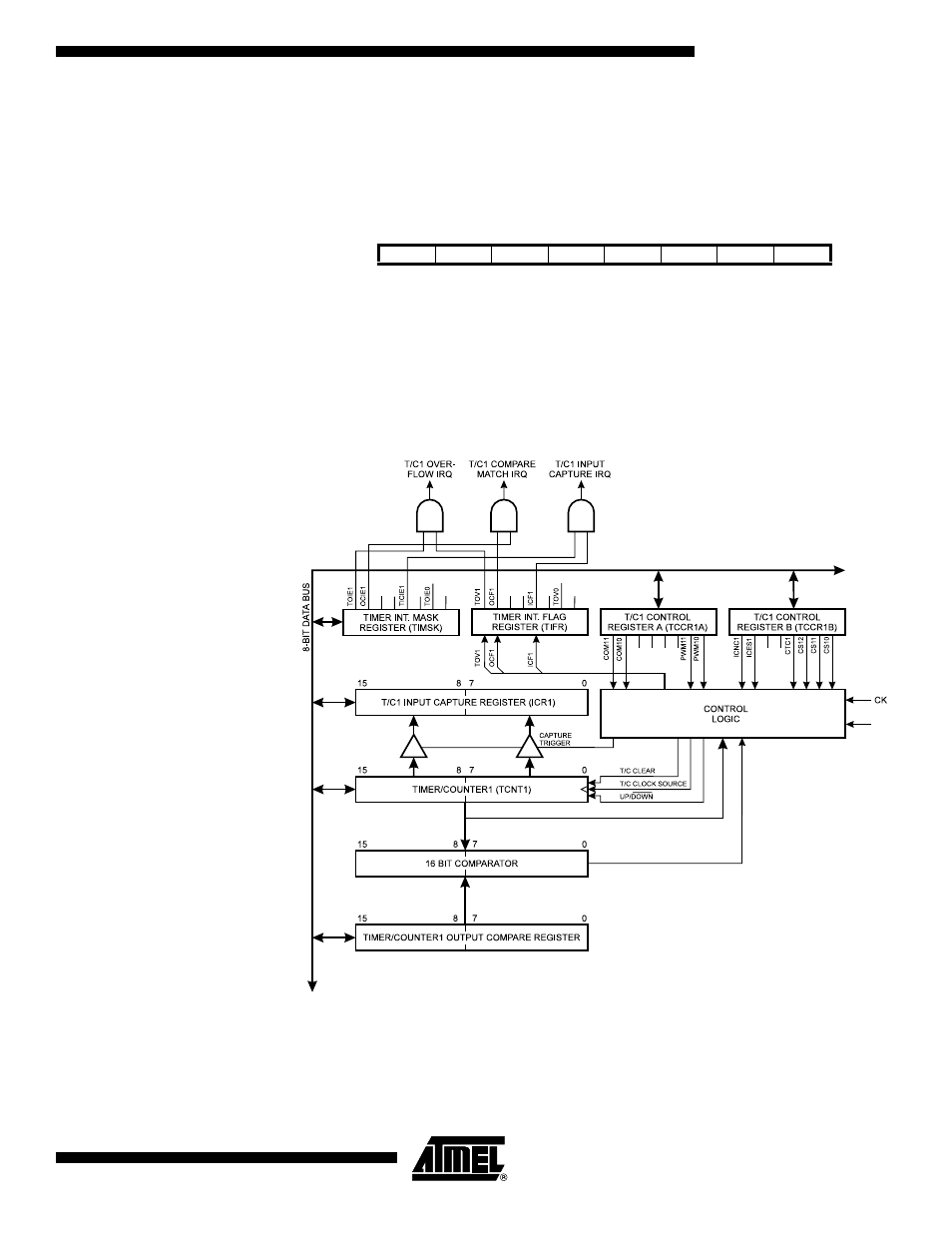
16-bit Timer/Counter1
Figure 32 shows the block diagram for Timer/Counter1.
Figure 32. Timer/Counter1 Block Diagram
The 16-bit Timer/Counter1 can select clock source from CK, prescaled CK or an exter-
nal pin. In addition, it can be stopped as described in the specification for the
Timer/Counter1 Control Register (TCCR1A). The different Status Flags (Overflow, Com-
pare Match and Capture Event) and control signals are found in the Timer/Counter
Bit
7
6
5
4
3
2
1
0
$32 ($52)
MSB
LSB
TCNT0
Read/Write
R/W
R/W
R/W
R/W
R/W
R/W
R/W
R/W
Initial Value
0
0
0
0
0
0
0
0
T1