Analog-to-digital converter, Features – Rainbow Electronics AT90LS4433 User Manual
Page 64
64
AT90S/LS4433
1042G–AVR–09/02
Analog-to-Digital
Converter
Features
•
10-bit Resolution
•
±2 LSB Absolute Accuracy
•
0.5 LSB Integral Non-linearity
•
65 - 260 µs Conversion Time
•
Up to 15 kSPS
•
Six Multiplexed Input Channels
•
Rail-to-Rail Input Range
•
Free Run or Single Conversion Mode
•
Interrupt on ADC Conversion Complete
•
Sleep Mode Noise Canceler
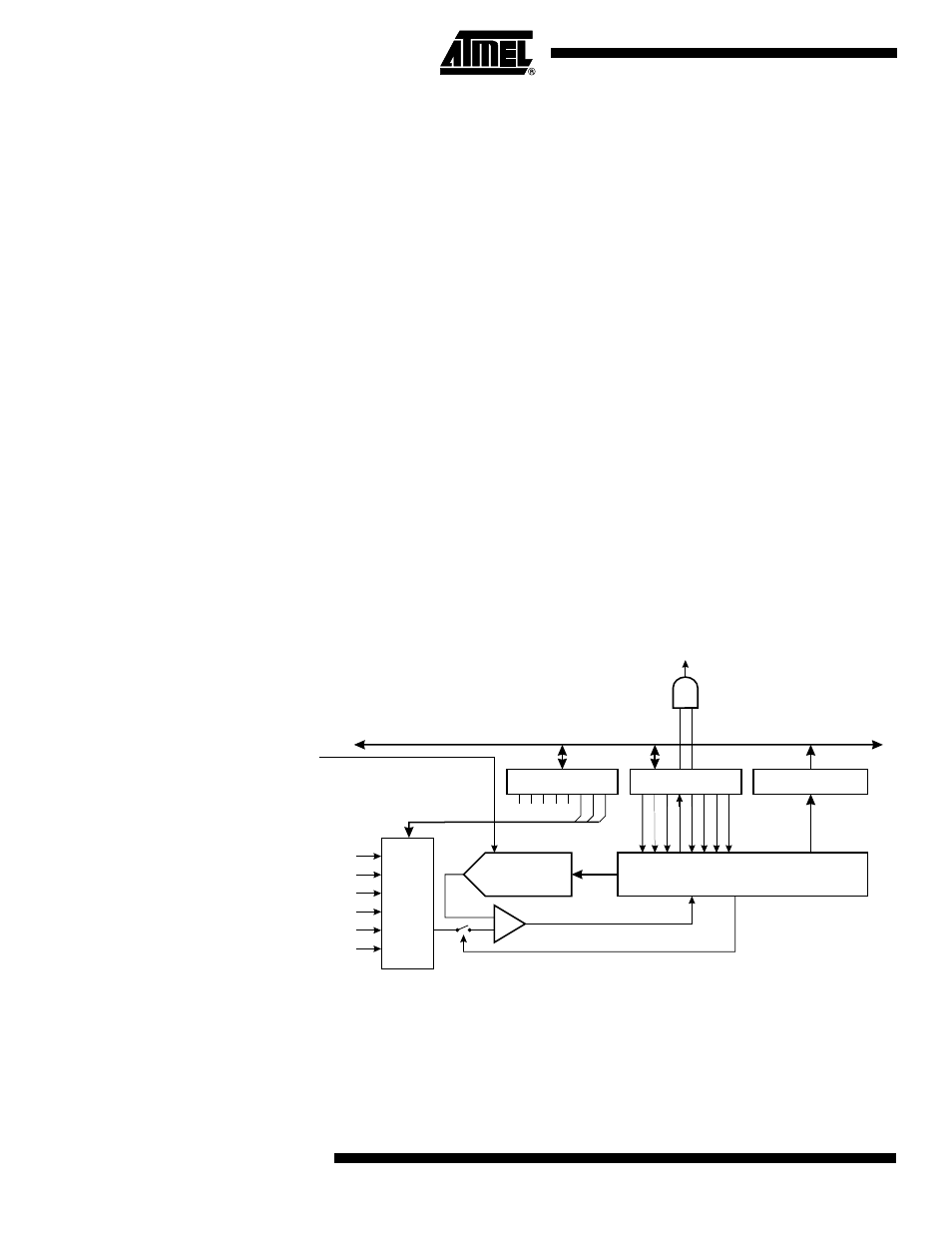
The AT90S4433 features a 10-bit successive approximation ADC. The ADC is con-
nected to a 6-channel Analog Multiplexer, which allows each pin of Port C to be used as
an input for the ADC. The ADC contains a Sample and Hold Amplifier, which ensures
that the input voltage to the ADC is held at a constant level during conversion. A block
diagram of the ADC is shown in Figure 44.
The ADC has two separate analog supply voltage pins: AVCC and AGND. AGND must
be connected to GND, and the voltage on AVCC must not differ from V
CC
more than
±0.3V. See the section “ADC Noise Canceling Techniques” on page 70 for how to con-
nect these pins.
An external reference voltage must be applied to the AREF pin. This voltage must be in
the range 2.0 - AVCC.
Figure 44. Analog-to-Digital Converter Block Schematic
ADC CONVERSION
COMPLETE IRQ
8-BIT DATA BUS
9
0
ADC MULTIPLEXER
SELECT (ADMUX)
ADC CTRL & STATUS
REGISTER (ADCSR)
ADC DATA REGISTER
(ADCH/ADCL)
MUX2
ADIE
ADIE
ADFR
ADSC
ADEN
ADIF
ADIF
MUX1
MUX0
ADPS0
ADPS1
ADPS2
6-
CHANNEL
MUX
CONVERSION LOGIC
10-BIT DAC
+
-
SAMPLE & HOLD
COMPARATOR
Analog
Inputs
External
Reference
Voltage