C-interface, digital potentiometers – Rainbow Electronics MAX5479 User Manual
Page 9
MAX5477/MAX5478/MAX5479
Dual, 256-Tap, Nonvolatile, I
2
C-Interface,
Digital Potentiometers
_______________________________________________________________________________________
9
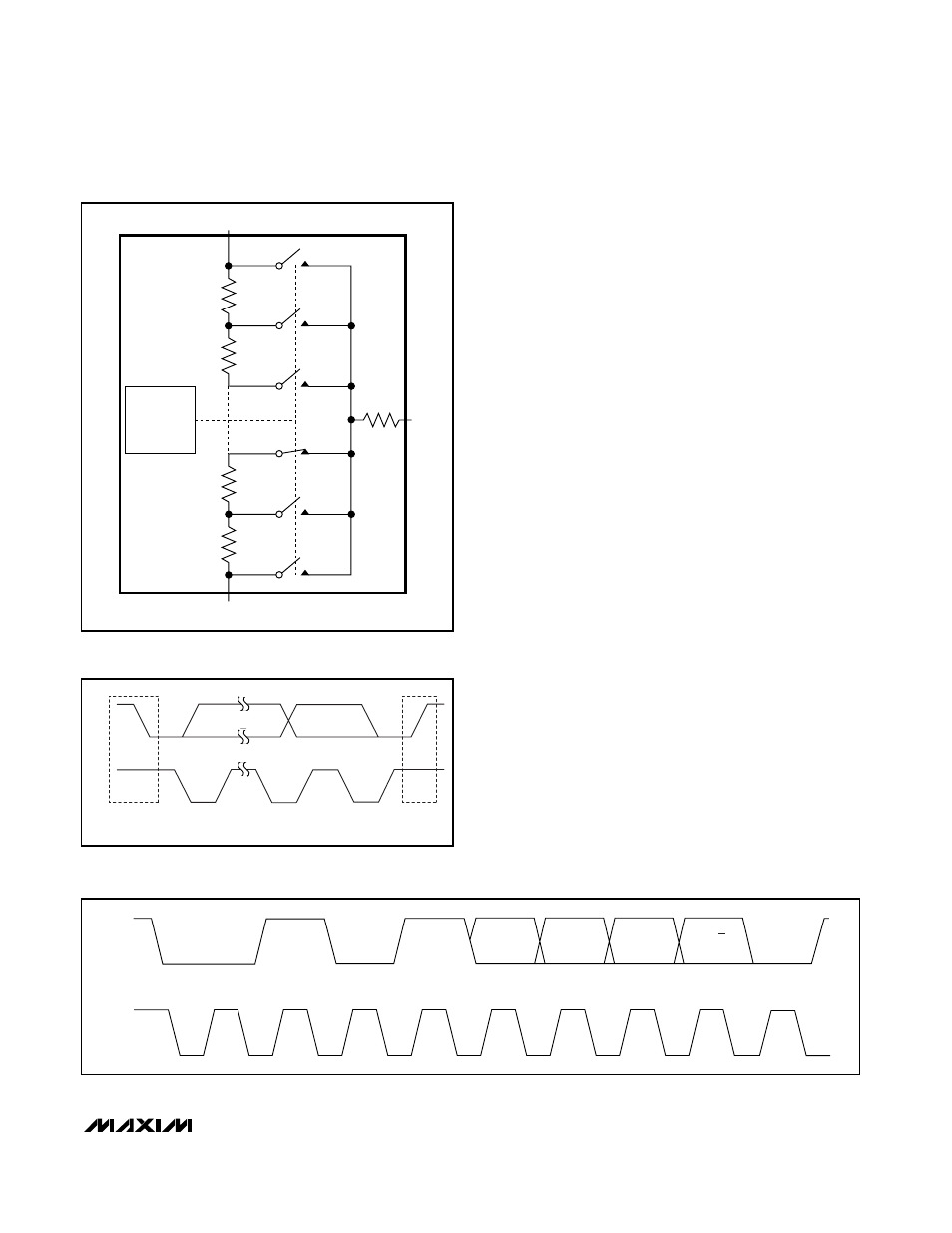
A simple 2-wire I
2
C-compatible serial interface moves
the wiper among the 256 tap points (Figure 2). A non-
volatile memory stores the wiper position and recalls
the stored wiper position upon power-up. The non-
volatile memory is guaranteed for 50 years for wiper
data retention and up to 200,000 wiper store cycles.
Analog Circuitry
The MAX5477/MAX5478/MAX5479 consist of two resistor
arrays with 255 resistive elements; 256 tap points are
accessible to the wipers, along the resistor string
between H_ and L_. The wiper tap point is selected by
programming the potentiometer through the I
2
C inter-
face. An address byte, a command byte, and 8 data bits
program the wiper position for each potentiometer. The
H_ and L_ terminals of the MAX5477/MAX5478/
MAX5479 are similar to the two end terminals of a
mechanical potentiometer. The MAX5477/MAX5478/
MAX5479 feature power-on reset circuitry that loads the
wiper position from the nonvolatile memory at power-up.
Digital Interface
The MAX5477/MAX5478/MAX5479 feature an internal,
nonvolatile EEPROM that stores the wiper state for ini-
tialization during power-up. The shift register decodes
the command and address bytes, routing the data to
the proper memory registers. Data written to a volatile
memory register immediately updates the wiper posi-
tion, or writes data to a nonvolatile register for storage
(see Table 2).
The volatile register retains data as long as the device
is powered. Removing power clears the volatile regis-
ter. The nonvolatile register retains data even after
power is removed. Upon power-up, the power-on reset
circuitry controls the transfer of data from the non-
volatile register to the volatile register.
A write-protect feature prevents accidental overwriting
of the EEPROM. Connect WP to V
DD
or leave open to
prevent any EEPROM write cycles. The wiper register
only updates with the value in the EEPROM when WP =
SDA
SCL
S
START
CONDITION
P
STOP
CONDITION
Figure 3. Start and Stop Conditions
MSB
START
SCL
SDA
ACK
A0
A2
A1
1
0
1
0
LSB
NOP/W
Figure 4. Slave Address
256-POSITION
DECODER
H_
L_
R
255
S
255
S
254
S
3
S
2
S
1
S
256
R
254
R
2
R
1
W_
R
W
WIPER
CODE 02h
Figure 2. Potentiometer Configuration