C-interface, digital potentiometers, Applications information, Table 2. command byte summary – Rainbow Electronics MAX5479 User Manual
Page 12
MAX5477/MAX5478/MAX5479
Dual, 256-Tap, Nonvolatile, I
2
C-Interface,
Digital Potentiometers
12
______________________________________________________________________________________
ADDRESS BYTE
COMMAND BYTE
DATA BYTE
1
2
3
4
5
6
7
8
9
10 11 12 13 14 15 16 17
18
19 20 21 22 23 24 25 26
27
SCL CYCLE
NUMBER
START
(S)
A6 A5 A4 A3 A2 A1 A0
ACK
(A)
TX NV V R3 R2 R1 R0
ACK
(A)
D7 D6 D5 D4 D3 D2 D1 D0
ACK
(A)
STOP
(P)
NOTES
VREG
0
1
0
1 A2 A1 A0 0
0
0
0
1
0
0
0
1
D7 D6 D5 D4 D3 D2 D1 D0
NVREG
0
1
0
1 A2 A1 A0 0
0
0
1
0
0
0
0
1
D7 D6 D5 D4 D3 D2 D1 D0
NVREGxVREG
0
1
0
1 A2 A1 A0 0
0
1
1
0
0
0
0
1
D7 D6 D5 D4 D3 D2 D1 D0
VREGxNVREG
0
1
0
1 A2 A1 A0 0
0
1
0
1
0
0
0
1
D7 D6 D5 D4 D3 D2 D1 D0
WIPER A
ONLY
VREG
0
1
0
1 A2 A1 A0 0
0
0
0
1
0
0
1
0
D7 D6 D5 D4 D3 D2 D1 D0
NVREG
0
1
0
1 A2 A1 A0 0
0
0
1
0
0
0
1
0
D7 D6 D5 D4 D3 D2 D1 D0
NVREGxVREG
0
1
0
1 A2 A1 A0 0
0
1
1
0
0
0
1
0
D7 D6 D5 D4 D3 D2 D1 D0
VREGxNVREG
0
1
0
1 A2 A1 A0 0
0
1
0
1
0
0
1
0
D7 D6 D5 D4 D3 D2 D1 D0
WIPER B
ONLY
VREG
0
1
0
1 A2 A1 A0 0
0
0
0
1
0
0
1
1
D7 D6 D5 D4 D3 D2 D1 D0
NVREG
0
1
0
1 A2 A1 A0 0
0
0
1
0
0
0
1
1
D7 D6 D5 D4 D3 D2 D1 D0
NVREGxVREG
0
1
0
1 A2 A1 A0 0
0
1
1
0
0
0
1
1
D7 D6 D5 D4 D3 D2 D1 D0
VREGxNVREG
0
1
0
1 A2 A1 A0 0
0
1
0
1
0
0
1
1
D7 D6 D5 D4 D3 D2 D1 D0
WIPERS
A AND B
Table 2. Command Byte Summary
Standby
The MAX5477/MAX5478/MAX5479 feature a low-power
standby mode. When the device is not being pro-
grammed, it enters into standby mode and supply cur-
rent drops to 500nA (typ).
Applications Information
The MAX5477/MAX5478/MAX5479 are ideal for circuits
requiring digitally controlled adjustable resistance,
such as LCD contrast control (where voltage biasing
adjusts the display contrast), or for programmable fil-
ters with adjustable gain and/or cutoff frequency.
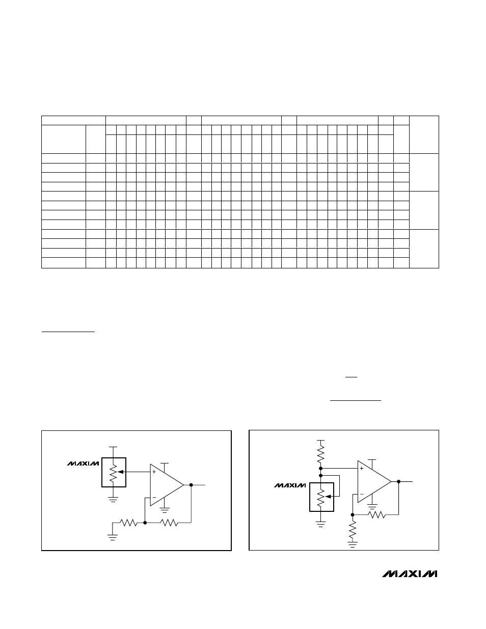
Positive LCD Bias Control
Figures 9 and 10 show an application where the
MAX5477/MAX5478/MAX5479 provide an adjustable,
positive LCD bias voltage. The op amp provides buffer-
ing and gain to the resistor-divider network made by
the potentiometer (Figure 9) or by a fixed resistor and a
variable resistor (see Figure 10).
Programmable Filter
Figure 11 shows the MAX5477/MAX5478/MAX5479 in a
1st-order programmable application filter. Adjust the
gain of the filter with R
2
, and set the cutoff frequency
with R
3
. Use the following equations to calculate the
gain (A) and the -3dB cutoff frequency (f
C
):
A
R
R
f
R
C
C
=
+
=
Ч
Ч
1
1
2
1
2
3
π
V
OUT
30V
5V
W_
H_
L_
MAX5477
MAX5478
MAX5479
MAX480
V
OUT
30V
5V
W_
H_
L_
MAX5477
MAX5478
MAX5479
MAX480
Figure 9. Positive LCD Bias Control Using a Voltage-Divider
Figure 10. Positive LCD Bias Control Using a Variable Resistor